Next to tires, brakes are the next most important system on your motorhome. A gasoline powered Class A motorhome will be equipped with hydraulic brakes, similar to your car, SUV or light truck. Diesel pushers or Super C coaches are heavier and will be equipped with air brakes that are better suited to handle that extra weight. For example, if a coach requires 200 HP to accelerate it from zero to 65 MPH in one minute, it will take ten times that force to bring the coach to a stop within 6 seconds – which is one tenth the time. Therefore, this coach needs to have a braking system designed to generate 2,000 HP to accomplish this. Hydraulic brakes don’t have the capability to stop heavier vehicles in a timely manner, which is why air brakes are used on larger vehicles such as class 8 trucks and diesel pusher motorhomes.
Air brakes aren’t something that the average owner is capable of doing any kind of service work on. That task is best left for certified professionals, such as the chassis technicians at National Indoor RV Centers, but there are still a few tasks that every owner needs to do and safety checks to perform other than just stepping on the brake pedal. But first, let’s start with a brief tutorial on how air brakes work.
Disc versus Drum
Drum brakes have been around forever. Disk brakes first showed up in the 1960s on passenger vehicles but it took another 40 years for them to show up on heavy duty trucks and motorhomes as air operated disk brakes. Drum brakes have their limitations. They function best at around 475 degrees, so when cold, you won’t have maximum stopping power. Their shoes begin to glaze around 800 degrees, so excessive use on mountain grades can cause them to fade and fail. They also don’t work well if they get wet – not until the drum can heat up and dry them out.
Disc brakes utilize pads that are in constant contact with the brake rotors. This keeps them warm and eliminates them from getting too cool so that they will have more stopping power when the brakes are applied. They also handle water better than drum brakes and are much harder to overheat because they are in the open air rather than allowing the heat to stay trapped inside a brake drum. The stopping power is much greater than in a drum brake and there is less maintenance due to a design that has less internal components to fail.
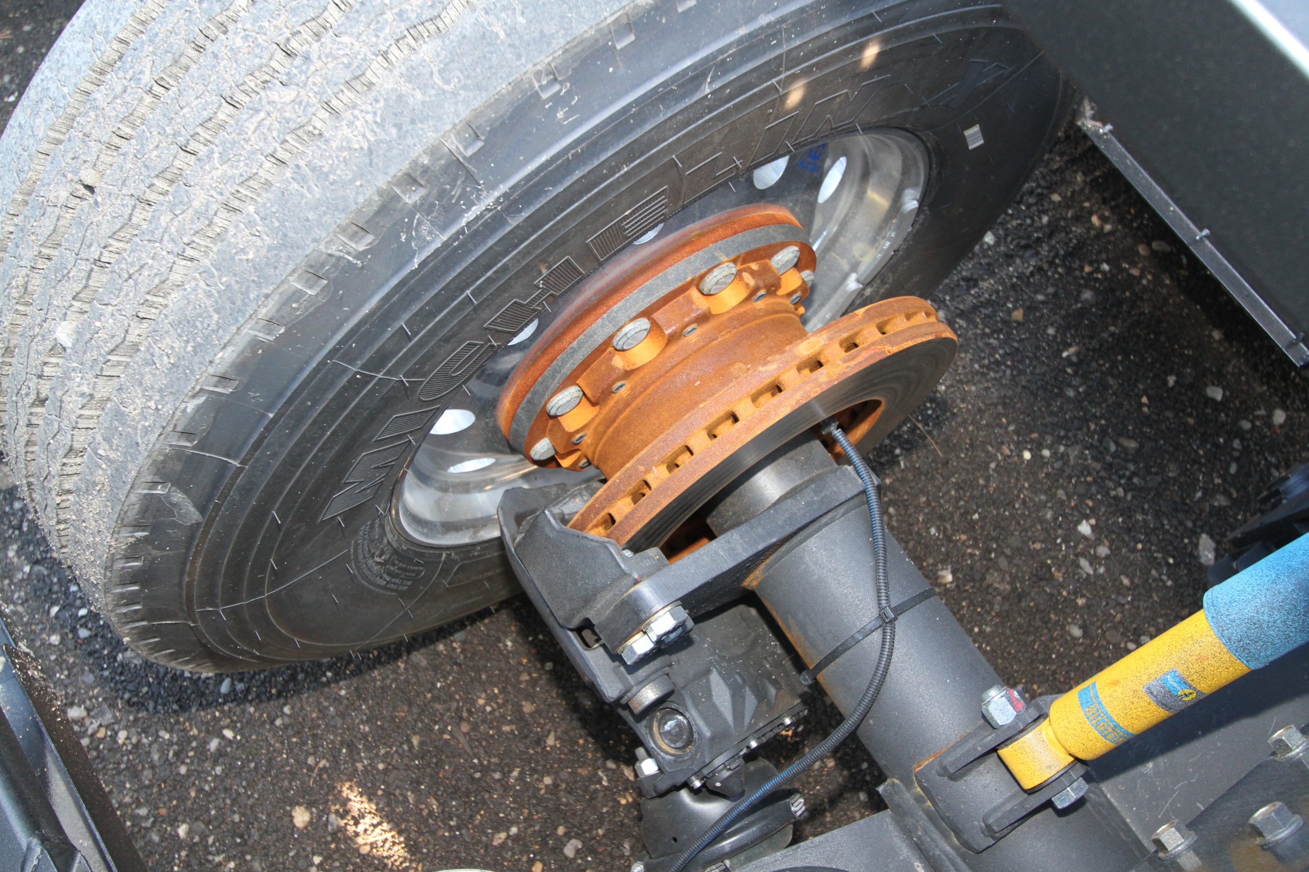
Disc brakes set up on a tag axle
RV Air System
Instead of hydraulic brake fluid, air brakes use compressed air supplied by an engine driven air compressor. Hydraulic brake fluid is hygroscopic, which means it attracts moisture. This moisture can turn to steam once the brakes heat up, resulting in a soft pedal. For this reason, hydraulic brake fluid should be changed every 2-3 years.
Air brakes don’t have that problem because the supply of air is always refreshed as the compressor intakes air and sends it to the air storage tanks. As the brakes are used, the air is constantly replenished. The air compressor’s governor will regulate the air pressure and the adjustable regulator is set to cut out between 115 PSI at a minimum and 135 PSI maximum. As the air pressure in the tanks drops by about 25 PSI, the regulator will tell the compressor to kick in and raise the pressure to the cutout point. Most chassis manufacturers set the cutout pressure at 130 PSI and the cut-in pressure to 105 PSI.
Moisture and Air
The air needs to be clean and dry. If moisture builds up in the system, it can cause issues with the O-rings, diaphragms and other components in the air system – not to mention freezing in cold weather. Any oil or other contaminants that exit the compressor can also damage diaphragms and other rubber components. For this reason, an air brake system will include an air dryer, which is a key component for any air brake system.
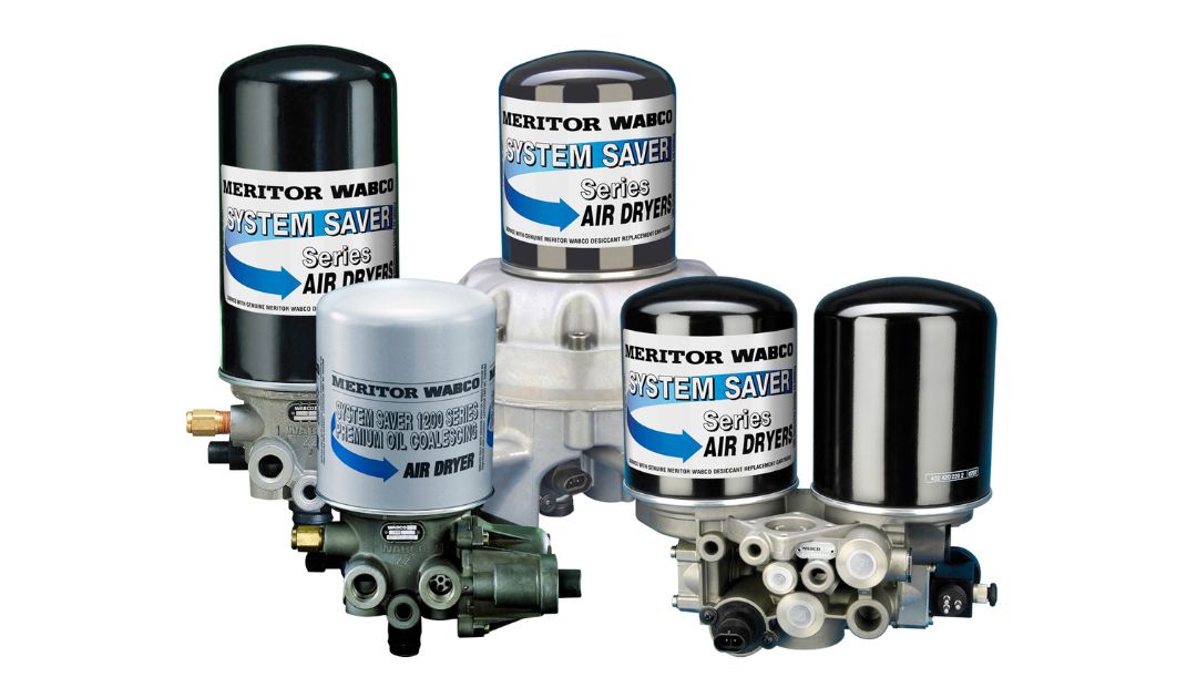
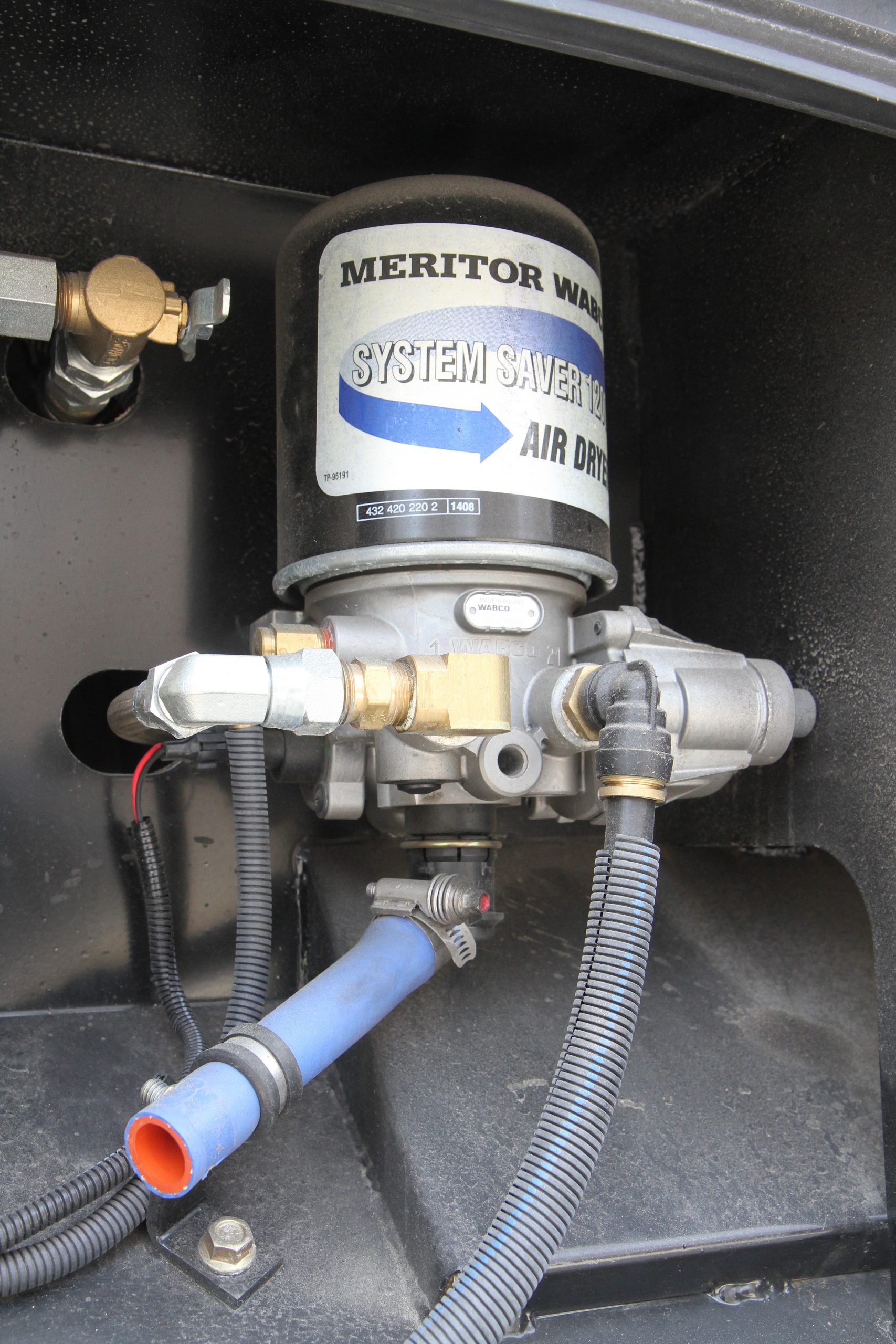
The air dryer is located between the air compressor and the air tanks and utilizes centrifugal force to spin off heavy sediment and moisture, trapping it in the bottom chamber of the dryer, which is heated to prevent freezing in cold temperatures. A secondary spin-on desiccant filter cartridge acts as a final filter to ensure that the air that exits the dryer is clean and moisture-free. As the compressor cycles and arrives at its cutout point it will send a pneumatic purge signal to the dryer and it will spit out the contents of the lower chamber to keep it clean. When that happens you hear a short blast from the rear of the coach as the dryer purges.
Air Tanks and Lines
Most systems utilize three air tanks, although there are always exceptions to the rule. Initially, the air goes to what is commonly called the “wet tank” but is also referred to as the “ping tank”. The air that arrives here expands and moisture is allowed to condense and settle in the bottom of the tank. This tank also acts as a buffer to remove any pulsation in the air being sent by the compressor. After this, the air goes to the primary and secondary air tanks. The primary tank is sometimes referred to as the “rear tank” because it supplies air to the rear axle brakes, which is where the lion’s share of braking is performed. The secondary tank may be referred to as the “front tank” because it sends air to the front axle brakes. It also supplies air for the air suspension system and any accessories, such as air horns. Both the primary and secondary tanks will have pressure gauges on the driver’s instrument panel as well as a low pressure alarm that will sound whenever the air pressure drops below 60 PSI.
Each tank has a safety valve designed to open at 150 PSI. They are also equipped with drain valves, which will have manual pull cables so that they can be drained. Oftentimes, they will also have automatic drain valves to eliminate any moisture from building up in the tanks. These automatic drains may be heated as well and operate on an internal pressure differential. The brake lines from the primary tank to the front brakes will be green in color, while the lines from the secondary tank to the rear brakes will be red in color. Air suspension lines are not required to meet these codes so they can be any color, but are usually black.
Brake Chambers and Wheel Components
Air drum brakes use brake shoes and drums similar to a hydraulic brake system, but the mechanism to operate them is quite different. Air brakes use a shaft with cams on the end. The shaft is twisted and the cams act upon the rollers on the end of the brake shoes to expand them. The shaft extends inboard and away from the wheel and is connected to a brake diaphragm chamber via an arm called a “slack adjuster”. Slack adjusters are adjustable so that the brake diaphragm only needs to move a certain amount to apply the brakes.
Today’s coaches use automatic slack adjusters, so under normal operating conditions, they should remain properly adjusted. If the coach sits for long periods of time, these cams can get rusty and the brakes will stick and not apply smoothly as the cam attempts to slide against the roller to apply the brake shoes and can actually freeze up in the locked position. In either case, it will be necessary to have the cams and rollers serviced and cleaned to restore smooth operation.
The brake diaphragms are fairly large in diameter, maybe 6-10”. A pushrod exits the center of the brake chamber and connects to the slack adjuster that operates the brake shaft. If the brakes are worn or the slack adjuster is not properly adjusted, the shaft will expose a red band that indicates excessive extension of the chamber’s shaft. If this happens, it’s time for brake service.
These brake diaphragms are used on the front steer and rear tag axles. Drive axles use a different style called a “spring brake”. The spring brake also acts as a parking brake and uses spring pressure to actuate. This ensures that your coach won’t roll away should the air pressure drop and also will stop the coach when driving in the event of a total failure of the air system. Spring brakes will automatically deploy when the pressure drops below 60 PSI.
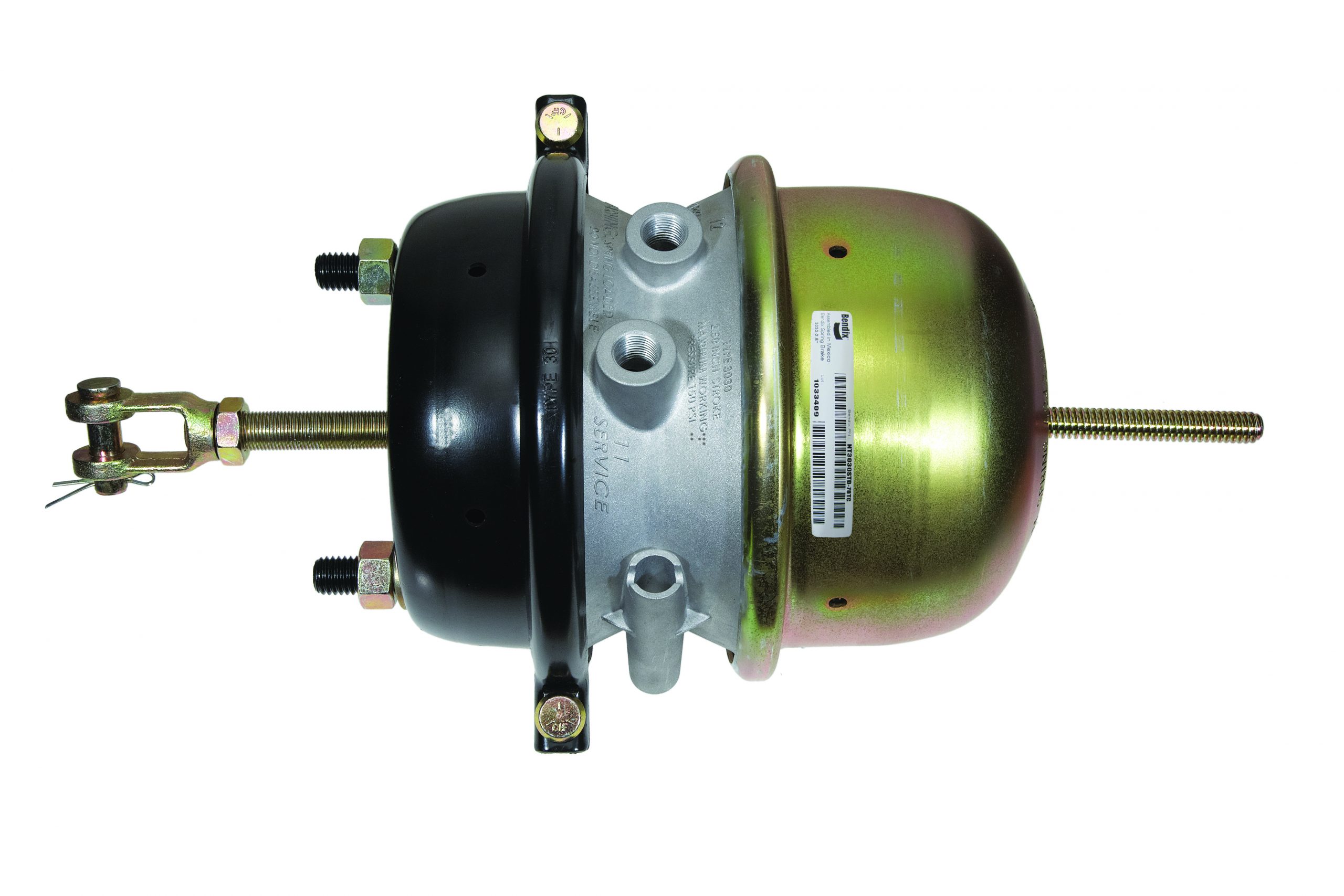
Spring brakes are used on the drive axle and function as a parking brake as well as a service brake.
To release the parking brake, you first need to ensure that you have adequate air pressure, and then push the yellow park brake knob in. This will apply pressure to the front chamber of the dual chamber spring brake to release the parking brake. So in effect, spring brakes use air pressure to release the brake rather than apply it. Spring brakes are only found on the drive axle, so it’s important to keep the drive axle on the ground and not raised on jacks when parked or else it won’t serve as a parking brake. Spring brakes are never used on the front axle because it would be impossible to steer with locked up front brakes should the air pressure drop while driving. During normal driving, air pressure is applied to the drive axle to stop the vehicle but that is done through the anti-compounding valve, which we’ll get into a bit later.
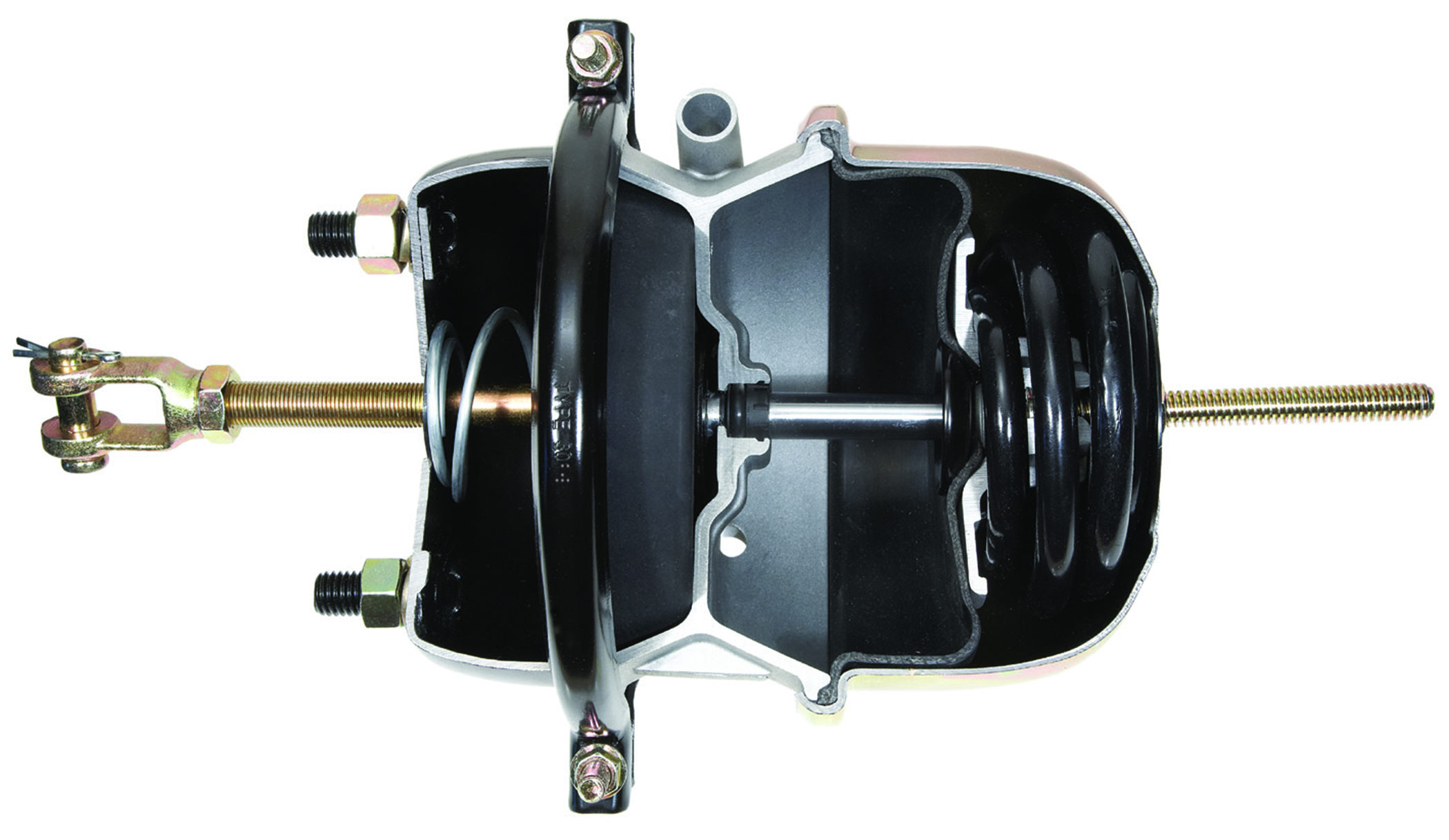
Cutaway view of a spring brake.
Disc brakes don’t use slack adjusters, brake shoes or rotary cams. They operate by using brake diaphragms to apply pressure to the calipers, some of which are totally sealed. They are self-adjusting but have a different and less complex method to achieve that.
RV Valves
Numerous valves are included to allow the brake system to safely bring the vehicle to a stop should a failure occur in the system. A one-way check valve is installed on the inlet to the primary air tank to prevent any air from draining back into the wet tank should a failure occur in that area. The secondary tank is equipped with a Pressure Control Check Valve (PCCV) if the system uses a regenerative style dryer, such as the Wabco, which utilizes dry filtered air to regenerate the dryer. This valve allows air to flow into the secondary tank at all times but will allow air to flow back to the wet tank only if the pressure is above 95 PSI. This will maintain a minimum pressure in the secondary tank but still allow the air dryer to use 10 PSI of clean air from the secondary tank during the dryer’s regeneration purge.
The dual foot control or treadle valve applies air to both the primary and secondary braking systems in response to the driver’s foot pressure. The primary valve is applied mechanically via the pedal, but the secondary valve is applied via air from the primary side. If the primary side has failed and has no air pressure, the secondary side is mechanically applied. Spartan sets their foot control valve to apply 3-5 PSI of air to the primary side before applying the secondary side. This applies the rear brakes slightly before the front and minimizes nose dive under braking.
Quick Release Valves are used on the secondary system to release air pressure from the front axle brake chambers quickly to disengage the brakes. On many brake systems, you can hear them operate as they make a honking sound when you release the brake pedal. Service relay valves are used on the primary system to improve brake balance on the longer runs from the foot pedal to the rear brakes. These relay valves are similar to the quick release valves but are connected directly to a reservoir for faster response and better control of the airflow.
The dash control valve, commonly called the push-pull valve, is used to deploy the parking brake. Pushing the yellow knob in applies air pressure to the parking brake to release it. Pulling out on the knob exhausts air pressure from the parking brake, allowing spring force to apply it. Should the system air pressure drop below 20 PSI, the yellow knob will automatically pop out – keeping in mind that the spring brakes have already been applied once the air pressure dropped to 60 PSI. If a massive failure of the air supply system occurs when driving, it should be noted that the rear brake will not totally lock up so that you lose control, but the brakes will bring the vehicle to a fairly abrupt stop. A Two-Way Check Valve supplies air from both the primary and secondary systems and will allow air from the dominant system to flow to the dash control valve so that you can release the parking brake if one system experiences a failure.
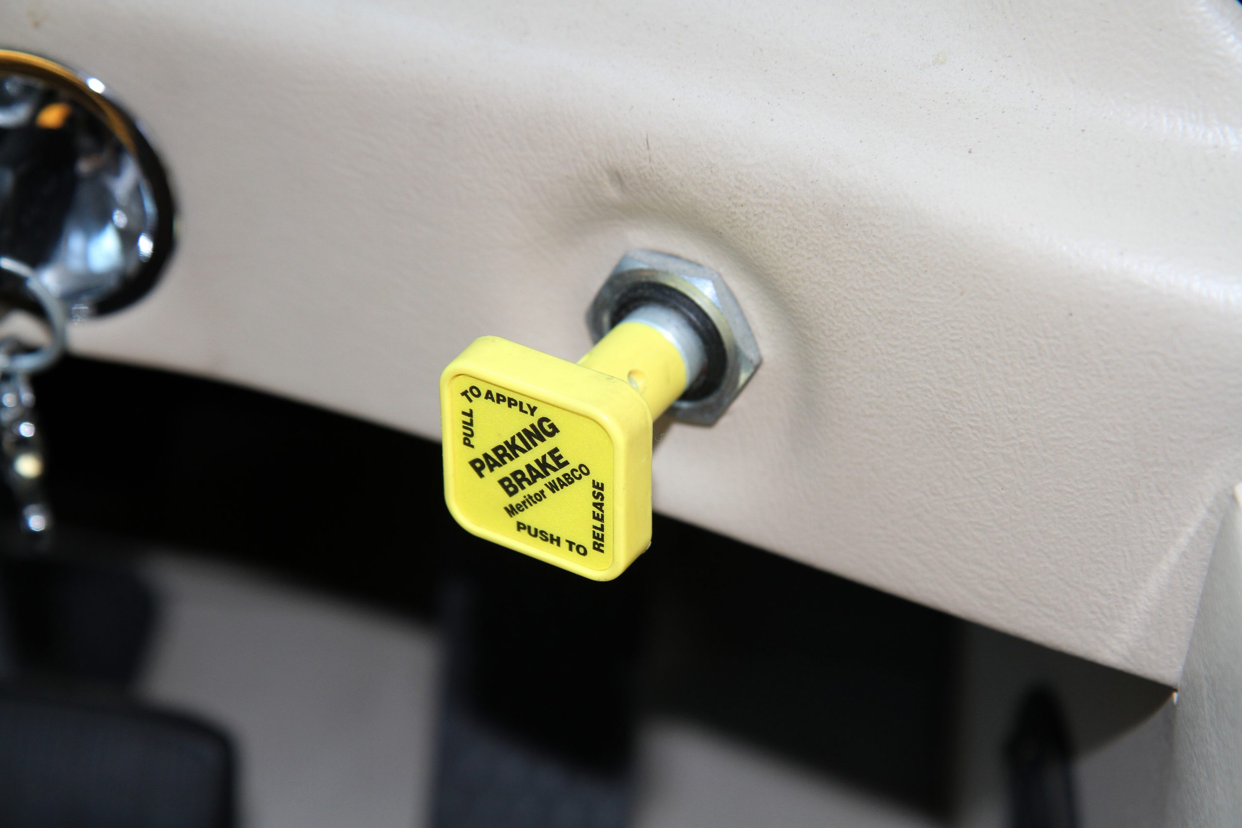
The yellow parking brake pull knob is commonly referred to as the push-pull knob.
Anti-Compounding Valve
Spring brakes use spring tension to apply the parking brake while an air chamber is used to release the parking brake. A second chamber is used for the service side of the system and is used to apply the service brakes when driving. The spring in a 30” spring chamber produces about 1,800 lbs. of force when parked. If the spring brake is connected to a 6” slack adjuster arm, it would produce 10,800 inch lbs. of torque. At the same time, the driver steps on the pedal and delivers 50 PSI to the service side of the spring brake. 50 PSI x 30 sq. in. = 1,500 lbs. force x 6” slack arm = 9,000 in. lbs. of additional force. This is compounding.
Compounding can lead to premature cracking or breaking of brake drums, bent chamber push rods, mounting studs torn out of the spring brakes, broken slack adjusters or torn spring brake mounting brackets on the axle. While not mandated by law, an anti-compounding system will prevent this from happening. This is accomplished via an Anti-Compounding Valve which is a Quick Release Valve with a Double Check valve built into it. This will apply air pressure to the parking brake chamber at the same time as air is applied to the service brake chamber, releasing the appropriate amount of park brake pressure in relation to the service brake pressure – preventing excessive pressure from damaging the spring brakes.
Inversion Valve Emergency System
An Inversion Valve is mandated by law as of 1975. Under normal conditions, this valve does not have to work. It only serves as an emergency valve in the event of a failure in the primary air system when driving. If the air pressure in the primary system drops to zero, the parking brakes will be held in the released position with air from the secondary tank.
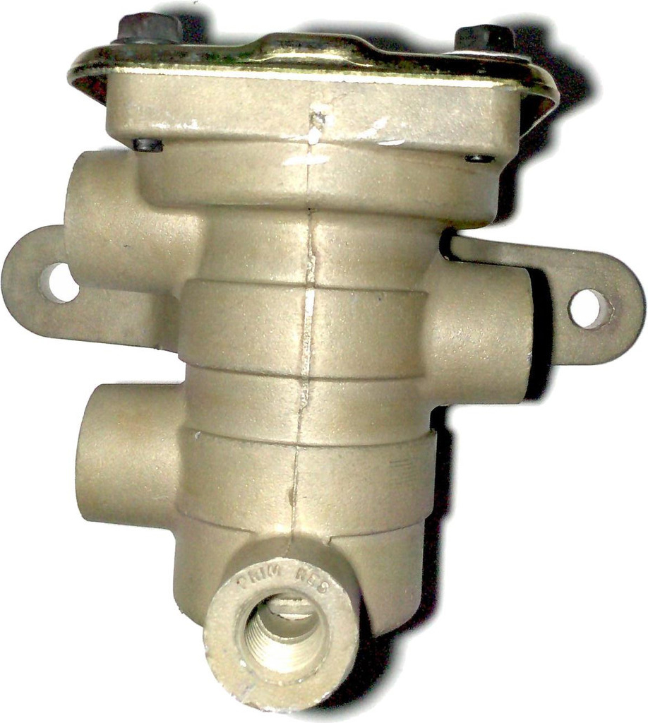
An inversion valve
The inversion valve receives the signal from the foot pedal and equally releases pressure on the spring brake chamber to apply the service brakes mechanically with power from the spring portion. When the brake pedal is released, air is restored to the spring brake chamber to release the brakes.
Anti-lock Braking Systems
Anti-lock Braking Systems (ABS) utilize electronic controls to release the brakes in the event of a wheel lock-up during a hard stop. A tooth wheel and electronic sensor are found on every wheel position and senses any wheels that have stopped turning. The electronic brain then communicates with a valve that will remove air pressure from that wheel position to allow it to resume turning. The valves operate quickly and typically can perform this up to 5 times per second. If you ever do a panic stop or begin to slide in slippery conditions, just keep your foot on the brake pedal and allow the ABS system to modulate the brake pressure. Backing off the pedal will be counter-productive and you’ll actually increase your stopping distance.
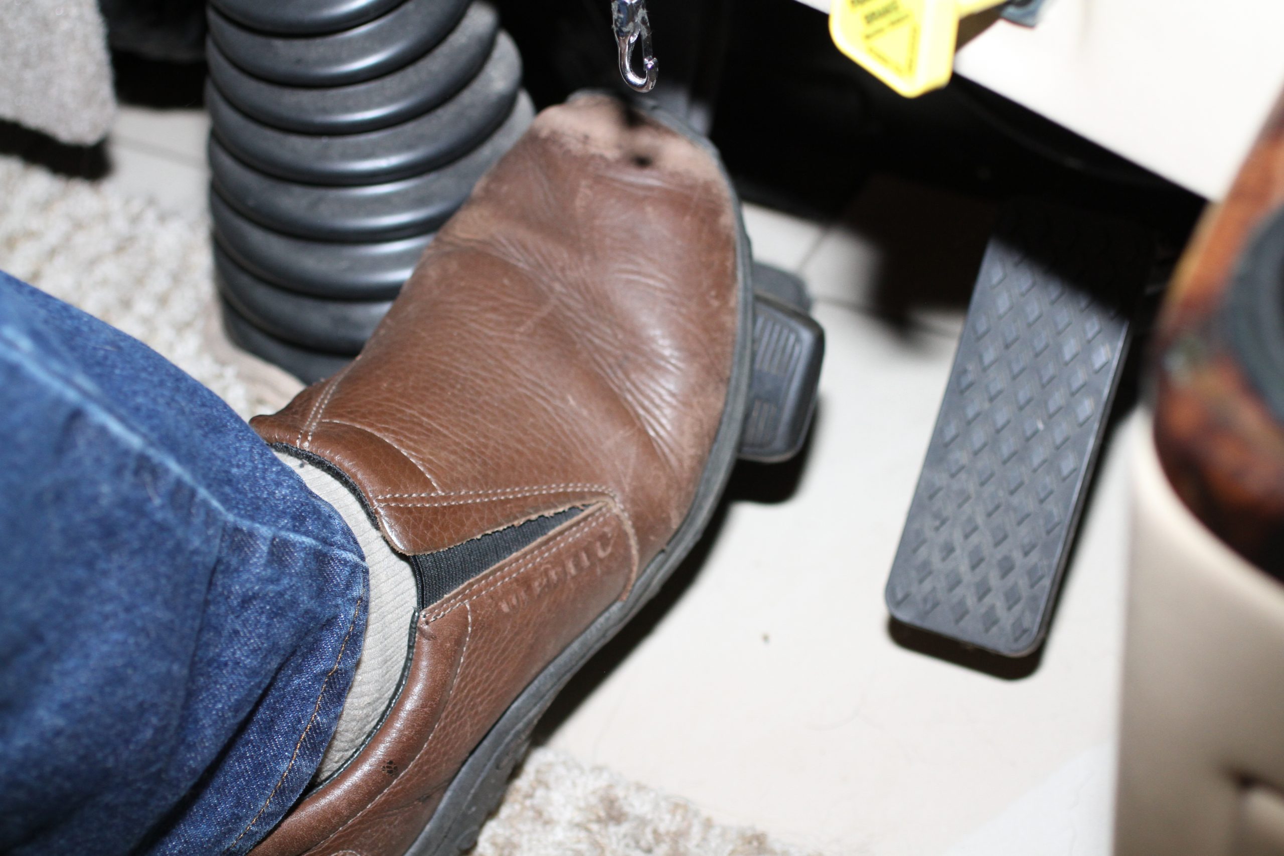
Part of the pre-trip inspection is to hold down the brake pedal while purging the ABS modules
Proper Startup Procedure
Automatic slack adjusters take a bit of effort to operate. If your driving style leans toward heavy engine brake usage and minimal service brake usage, the odds are good that your service brakes will not be in proper adjustment and won’t be very effective when you need to seriously use them. Drum brake systems require at least 65 PSI of braking pressure to operate, which is a fair amount of brake pedal pressure. Disc brakes aren’t quite as severe and only require about 20 PSI to operate. A quick, firm application of the brake pedal will help to keep them adjusted.
ABS systems rarely get used and are more like an insurance policy in that they are invaluable if the need ever arises. However, sitting idle isn’t the best for any vehicle component. The ABS ejector ports can freeze up from lack of use over time. Spartan Chassis recommends using the following procedure to exercise the ABS system every time you start the coach:
- Apply the foot brake with medium pressure and hold.
- Turn the ignition key on but do not start the engine, continuing to hold the brake pedal down.
- You should hear four or six pops (one for each wheel) as each ABS modulator cycles through and exhausts the port.
- Start the engine and release the parking brake.
- Apply the foot brake with full pedal pressure, then release it. This will operate the self-adjusters to keep your brakes in proper adjustment.
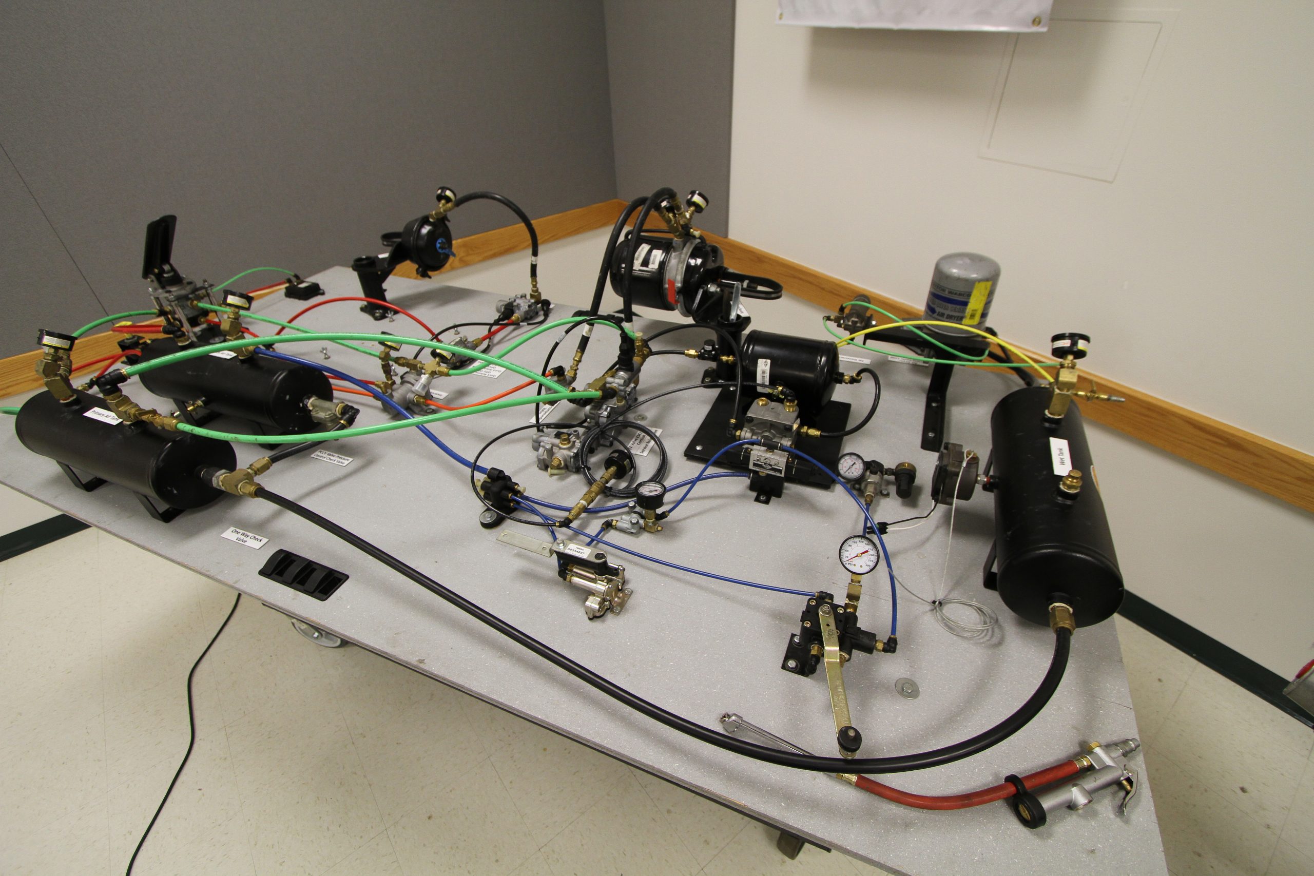
This training tool at the Spartan Training Center contains all of the components required to create a complete braking system. The various pressure gauges and test points assist the trainee in learning exactly how the various components operate.
Checking the Air Tanks and Valves
Most coaches are equipped with lanyards to operate the manual air tank drain valves. Generally, these are located inside a wheel well but exceptions exist so check your manual for the exact location of the lanyards or valves on your particular coach.
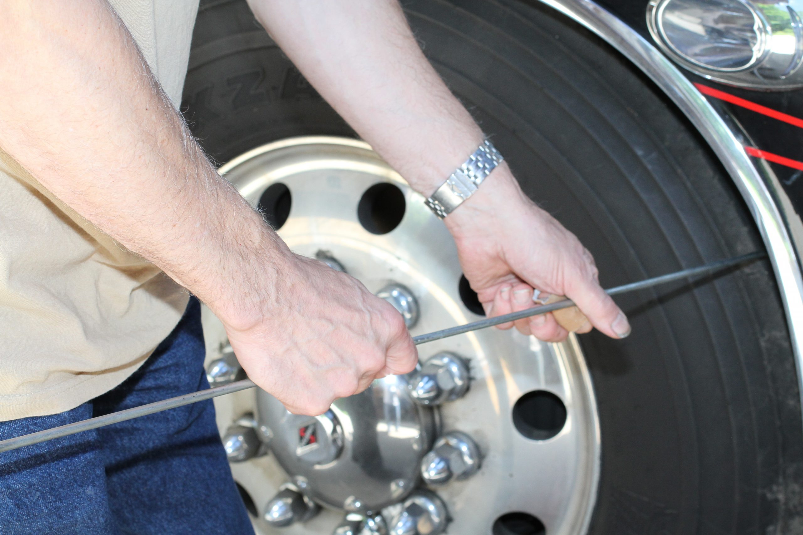
Many air tank drain valves are actuated by pulling lanyards within the wheel wells. For safety reasons, it’s important to use a device such as an awning hook to operate these lanyards.
Modern coaches are equipped with an air dryer that provides clean, dry air to the system so you may feel the need for manually draining the air tanks is an exercise in futility, but that is not the case. If the air tanks are drained in the correct procedure, it serves as a diagnostic tool to check the integrity of your air system. First of all, if your air dryer is functioning correctly, you will see little or no moisture being ejected from the air tanks when you pull the lanyard. If you do, it will indicate that your air dryer needs to be serviced and the desiccant cartridge replaced. Secondly, by using the following procedure you will be able to verify that your various check valves are operating correctly:
- Make sure both air gauges are reading 70 PSI or less. If the gauges read higher, bleed the system down by pumping the brake pedal until the gauges read 70 PSI or less.
- Start the engine and run at high idle (1200 RPM or higher) until the air dryer purges in the back of the coach
- Turn the key to the “off” position to stop the engine. Then turn the key back to the “on” position so that the gauges will function. Do not start the engine.
- Never reach your arm into a wheel well or crawl beneath the coach when you drain the air tanks. If you can’t safely reach the lanyards with your awning hook, use some way – such as jack stands – to support the vehicle. Sometimes you can just turn the steering wheel to give you more access to the wheel well.
- Locate your lanyard or petcock locations. There should be three of them, one to each tank although some tanks are split into two separate compartments so there may be two drain valves on one tank.
- Drain the air completely from the wet tank. This should be identified by a clear or gray lanyard cable.
- Go into the coach and check the gauges. They should not read zero. This will ensure that the check valve between the primary and wet tank is functioning properly.
- Next drain the primary tank completely. This should be identified by a green lanyard cable.
- Check the air pressure gauges once again. The rear gauge (primary system) should be reading zero and the front gauge (secondary system) should not be reading zero. This will ensure that the check valve between the primary and secondary tank is functioning properly.
- If either of these valves is not functioning as they should, take the coach to a service center to have these valves serviced or replaced.
- Now drain the secondary tank completely. This should be identified by a red lanyard cable.
- Check the gauges again. Both gauges should now read zero.
- If significant moisture was found when draining the tanks, it’s time to have the air dryer serviced. The desiccant cartridge typically lasts for 2-3 years, but the lifetime will vary according to how often the coach is driven and how humid the environment is. The main purpose of the tank draining procedure is to check for when the moisture begins to appear, which indicates when the dryer needs to be serviced.
- Make sure that all of the petcocks or drain valves are closed and restart the engine. Run at a fast idle until the air dryer purges. The system should now be ready for operation and both gauges should read somewhere around 110 PSI.
Lastly, there is an “official” pre-trip inspection. I realize that most motorhome owners simply start the engine, raise the jacks, bring in the slides and hit the road, but a true pre-trip inspection is recommended by the federal DOT to verify that the coach brakes are functioning correctly.
In fact, this procedure would probably be on a CDL test. I’d wager that most truckers don’t follow this either and it’s not something I do every morning that I leave – but it can be helpful. It will show you if your braking system has any leaks or has any issues such as a restricted air dryer or sub-standard compressor that can result in not making enough air, so this can be a good test if you suspect anything. A typical pre-trip inspection should consist of the following procedure:
- Manually drain the air tanks.
- Run the engine at fast idle. The air pressure should go from 50 PSI to 90 PSI in less than 3 minutes.
- The air governor should unload the compressor at a minimum of 115 PSI and a maximum of 135 PSI.
- Fan the brake pedal to drop the air pressure to 80 PSI. If the governor is functioning correctly, the pressure should begin to rise.
- Continue fanning the brake pedal. The low air pressure alarm should sound at approximately 60 PSI.
- Build up a full head of air pressure and switch off the engine.
- Release the spring (parking) brake.
- Apply full brake pedal pressure and hold.
- Hold this pedal pressure for at least 2 minutes. The air pressure should drop no more than 3 PSI per minute. If there is excessive pressure loss, you have a leaky fitting or component in your brake system – possibly even a leaky brake diaphragm. Note that this assumes that your air-ride suspension is fully inflated and you are no longer using chassis air to inflate the airbags. If your pressure drops without applying the brake pedal, you may have a leaky air bag in your suspension.
When you get right down to it, air brake systems are filled with safety features and the ability to safely handle many failures that may occur in the system. With just a little bit of understanding of the basics and a bit of effort put into performing the various tests and checks, you’ll be able operate your air brake equipped coach safely and be able to determine if something isn’t quite right. This way, you’ll know when to take it in for service and have the issue corrected.


