Last month we began our tutorial on RV electricity explaining the basics of electricity (the boring part), how the electrical panels are configured and briefly touched on generators. This month is part two of a three-part series and we’ll get a bit more interesting as we help you understand batteries, transfer switches and inverters. Finally, we’ll conclude this series next month with the final installment that will cover more advanced topics such as solar power, surge protection and energy management systems.
Transfer Switches
Sometimes the 120 volt devices in your motorhome need to be powered when you are not plugged into a campground pedestal, frequently referred to as shore power. When shore power is unavailable, the on-board generator set can be used to power these devices. Generators can be used in a number of situations, such as camping in remote areas where access to power is not available. A number of systems, such as lighting, water pumps and fans, are powered by your 12 volt battery. However, there will come a time when these batteries need to be recharged. The on-board generator can be used to power the coach’s battery charging system in the absence of shore power. Another use for generators is to power the rooftop air conditioners to make for a more comfortable motorhome interior in hot weather.
Your RV’s 120 volt electrical system is fed through a central distribution panel where all of the circuit breakers are located. In order to power this panel from two different power sources we can choose one of two methods. The first is the more cost effective and least costly and is commonly used in lower cost travel trailers. That method entails hard wiring a power cord to the breaker panel’s inputs. When not plugged into shore power this cord can be plugged into a generator set outlet to provide power to the RV’s electrical systems. While this method is inexpensive, it’s less convenient because you have to physically switch the plug from the shore power receptacle to the generator receptacle. The second method is to install an automatic transfer switch.
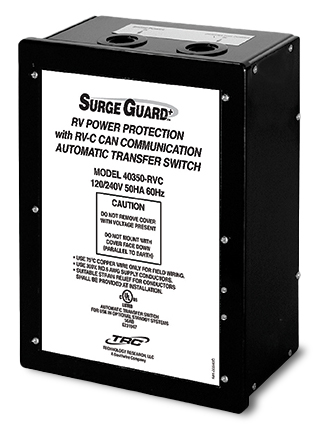
Automatic Transfer Switch
A transfer switch is basically a three way switch that switches between two inputs and connects them to a single common output. An automatic transfer switch mounted in a motorhome is located prior to the breaker panel where it can intercept the shore power cord feed to the breaker panel. The output of the transfer switch then goes to the main breaker of the breaker panel. The shore power cord is connected to one of the inputs in the transfer switch while the output from the generator is hard wired to the transfer switch’s second input. Transfer switches will connect one of these two inputs to the switch’s output. Manual transfer switches need to be manually switched by moving the switch lever on the box and are uncommon in a motorized RV. Automatic transfer switches commonly used in an RV will do this automatically and are logic controlled to switch under a given set of conditions. Generally automatic transfer switches will default to the generator inputs and are mechanically held. Once shore power is present the magnetic coils will pull the switch’s contact relays over to the shore power side. This is why you typically hear that clunk when the switch engages shortly after connecting to shore power. As soon as the shore power is no longer present the switch will revert back to its generator priority position.
Automatic transfer switches contain relays that switch between the two power sources. The magnetic coils that activate the relay contacts are engaged when the circuitry detects the presence of shore power. If you are running as large load the current across these contacts is substantial. When shore power is connected or disconnected, a large arc can occur across the contacts. Eventually this can pit the contacts and cause them to weld shut, rendering the transfer switch inoperative. If you have large loads operating it’s a best practice to switch them off before disconnecting from shore power to prevent this from happening. If your contacts do pit it is possible to file them clean by shutting off all power sources to the transfer switch, removing the cover and filing the contacts with some 120 or 220 grit sandpaper to clean them up. If they are too far gone the switch will need to be replaced or repaired. Another point of maintenance is to inspect the lug connections where the wires connect to the switch. The Allen head screws can loosen up over time, allowing loose wiring connections that can cause arcing in the connectors. It’s a good practice to inspect these connections every year or so and tighten them if necessary.
Generators
A motorhome has wheels, which means it’s mobile and doesn’t have to stay in one place forever. This means that shore power isn’t always available. Fortunately, most motorhomes are equipped with an on-board generator set to provide AC power when you are driving or when camping in a location that has no shore power. On some units you’ll find this generator in a basement compartment designed to provide adequate ventilation, intake air for the engine and a way to get rid of exhaust fumes. If you have a diesel pusher motorhome the odds are that your generator will be mounted in the very front of the coach, usually on a slide-out mechanism for ease of service. Permanently mounted generators are larger, heavier and quieter than their smaller portable cousins.
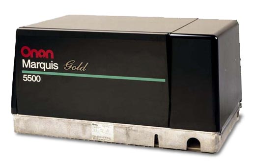
Onan gasoline powered generator
Gasoline powered Class A motorhomes will be equipped with a generator powered by a gasoline engine. The generator shares the same fuel tank as the vehicle engine but uses a separate fuel pickup within that tank. Usually these pickup tubes are cut short so that the generator will not run if the fuel level gets below a ¼ tank but this amount can vary from one manufacturer to the next. The reason for this is so that you can’t totally drain your fuel tank while dry camping. The ¼ tank remainder ensures that you will always be able to start your RV’s engine and drive to a refueling location. These generator sets are designed to slide into a basement compartment that is designed for that purpose so access to the controls and engine service points is done through the removable side cover on the generator, which also serves to contain the cooling airflow and add additional sound deadening capability.
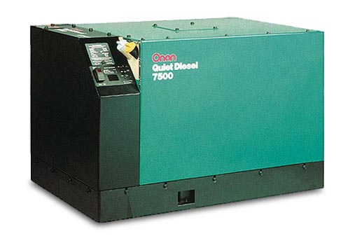
Onan Quiet Power diesel generator
Diesel powered generators can be found on motorhomes that are powered by diesel engines. Some of the entry level class A diesels are really front engine gasoline chassis with a diesel engine in place of a gasoline engine. Also, many smaller B+ and Super C motorhomes are now being made with small diesel engines. In this case the diesel powered generator will be fairly small (in the 4 KW to 7 KW range) and will be mounted in a side compartment in the same fashion as the gasoline powered generators. On a rear engine diesel pusher, the front of the coach is clear of engines and radiators. In this case you’ll find a diesel powered generator that is mounted in the front cap on a set of slide rails. The generator can be slid forward out of the coach to allow better access for servicing the unit. These units generally start at around 7,500 watts and run up to 10,000 or 12,500 watts in size. Some older motorhomes used a propane powered generator that ran off the RV’s on-board LP tank. However, these are rare and less desirable because the limited capacity of the propane tank didn’t give the generator a very long running time before the LP tank was empty. Used coaches with propane powered generators are very hard to sell and their resale value reflects this.
Generators that are rated up through 8,000 watts are usually single pole 120 volt-only generators, referred to as “in-phase” generators because both windings are in the same phase. Larger generators, 10,000 watts and up are two pole split-phase 120/240 volt generators with a center tap neutral. Because motorhomes rarely have any 240 volt appliances you may think that this arrangement isn’t needed. But if you refer back to our split phase 120/240 diagram you’ll recall that each phase has a given amount of amps available. That’s what allows you to balance your load and eliminate the heavy wiring required for a 10KW generator, which would output 83.33 amps if it was an in-phase design. Note that a 50 amp electrical service is equivalent to 12,000 watts, which is the size generator required if you needed to supply a full 50 amps to your RV’s breaker panel.
Frequency and RPM
Earlier we saw a graph of the AC and DC waveforms. The vertical height of the waveform represented voltage. But we also need to control just how fast this electrical pulse occurs. This is plotted horizontally on the graph and is referred to as frequency, which is labeled as Hertz. In North America all electrical power is 60Hz while in Europe and most of the rest of the world electrical power runs at 50 Hz. Hz is basically a counter of how many electrical pulses or waves occur in one second. A small portable generator must run at 3,600 RPM in order to produce 60 Hz of electrical power. When you divide 3,600 revolutions per minute (RPM) by 60 seconds we get 60 revolutions per second. It takes two field coils, a north pole and a south pole, to create the magnetic field necessary to create electricity. There are two field coils in a small portable generator, so it takes one revolution of the generator to create one Hertz. When the generator is turning at 3,600 RPM it will produce 60 Hz. It doesn’t matter what size output the generator makes but the speed at which it turns is important.
Small portable generators tend to be noisy because an engine running at 3,600 RPM isn’t very quiet. They were designed to be light and portable. In a motorhome this isn’t important because the generator doesn’t need to be lifted because it will be mounted into the RV. What is important is the noise level. If we add a second set of field coils to our generator, we will double the frequency to 120 Hz when running at 3,600 RPM, which isn’t good and will burn up our electrical devices. But if we take that same 4 pole generator and slow it down to 1,800 RPM we will still have 60 Hz. It’s just that we are passing twice as many magnets during the same revolution so by reducing the number of revolutions by half we will still maintain 60 Hz. This is the way many RV generators are set up. The 1,800 RPM speed of the engine allows for quieter operation. Because we don’t have to lift this generator we can also add a nice large muffler to it. The big drawback is that we have to use a larger engine. A small 8 HP engine is capable of creating 3,500 watts at 3,600 RPM but when you slow it down to 1,800 RPM it will only put out around 5 HP, which isn’t enough. By going with a 12-14 HP engine, we will still have 8 HP available at 1,800 RPM to then make our 3,500 watts of power. This means that the engine will be physically larger, weigh more, be quieter and more durable, and cost more than a smaller engine that is running higher revs. But the gains are well worth it in an RV application. Large utility power plants carry this even further and can use as many as 24 field coils in their generation systems so that they only have to turn 300 RPM. Less RPMs means greater life but more weight and size, while less magnets means less weight and size but greater speed and wear.
There is one exception to this RPM rule for generators. There is a trend towards inverter generators which use a variable speed engine to produce DC current to an inverter board within the generator. The inverter will convert DC power to AC power electronically. A DC generator is not sensitive to its RPM because the inverter controls the frequency and voltage electronically. These are smaller generators, such as the Onan Quiet Diesel (only up through 8KW) and small portables such as the Honda EU series. The benefit to this is that the generator can run at a lower speed when the demand for power is light, ramping up to higher speeds as the demand increases. This will minimize fuel consumption and supposedly reduce the noise level, although some models can actually be louder at full song compared to a traditional 4-pole generator. The electronic circuitry of the inverter will regulate the output voltage at a steady 120 volts and the frequency at a consistent 60 Hz.
Effects of Altitude
Any engine will produce a given amount of power based upon how much fuel and air it consumes, and higher power loads and RPMs consume more fuel. Because fuel and air are in a somewhat constant ratio, the engine will require more air at higher power outputs. But as we drive our motorhomes up into higher elevations, the air gets thinner and the engine loses its ability to produce its maximum rated power. This results in a corresponding drop in generator output wattage.
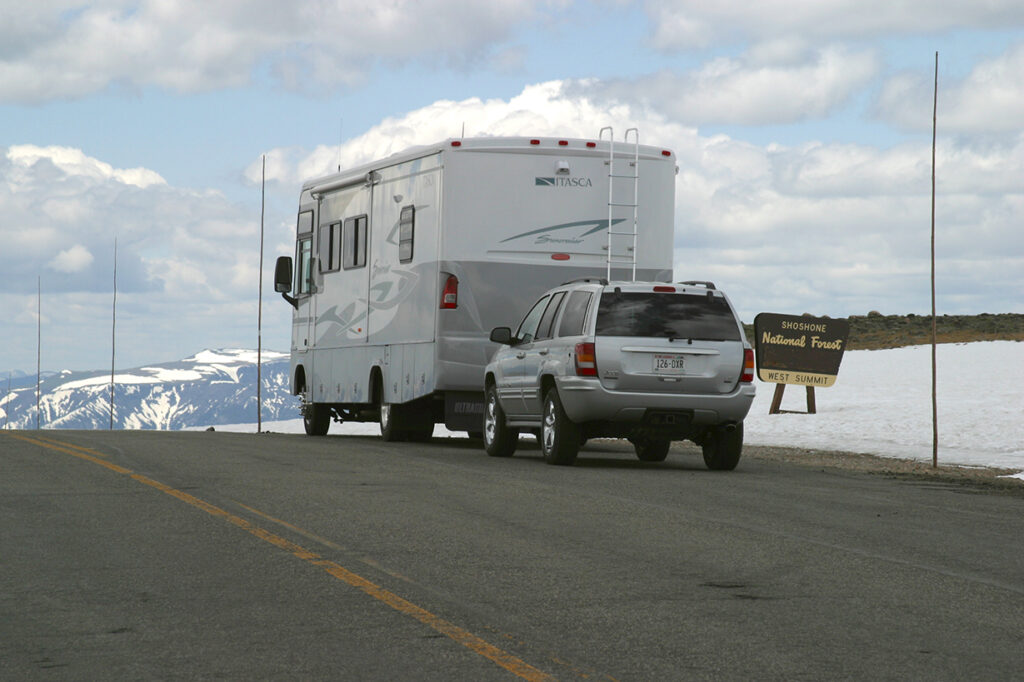
High-altitude image of a Suncruiser at 11,000 feet
Different engines will react in varying amounts. For instance, the output wattage of the Onan Marquis Gold series of gasoline powered generators will lose 3.5% for every 1,000′ in altitude gain over 3,000′. The Onan Quiet Power Diesel 10,000 watt will derate 3.5% for every 1,000′ over 500′ and it further derates by 1% for every 10° F increase in temperature over 85° F. A good rule of thumb for most gensets is that you will lose 10% of the rated output every time you gain 3,000′ in altitude. This means that a 7,500 watt generator running at 9,000′ of altitude will only be capable of producing a bit over 5,000 watts at that altitude.
Diesel engines are pretty well able to handle the fuel injection requirements at higher altitudes but carbureted gasoline powered engines do not have that luxury. The Onan Marquis Gold series of generators uses carburetors that have an altitude compensation adjustment on the carburetor. By dialing in a higher altitude you will lean out the mixture to prevent spark plug fouling and excessive smoke. It is very important that you also dial it back when descending to lower altitudes or else the engine will run lean and you can burn the engine’s valves.
Breaker Panels
Breaker panels serve two functions. They provide a central distribution center for all of the various circuits to tie into the incoming power supply, and they also provide overload protection to prevent electrical fires from any short circuits. Fuses are pretty much a thing of the past on high voltage circuits in RVs, so resettable circuit breakers are provided in their place. Breaker panels, also called power distribution centers, are mounted in an accessible location inside the RV so that the circuit breakers can be reset as needed. They are also used to de-energize a given circuit so that circuit can be safely worked upon without endangering the operator.
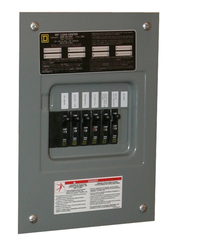
A 30 amp in-phase breaker panel
Circuit breaker panels are going to vary quite a bit from one brand to the next as well as between a 30 amp and a 50 amp service. A 30 amp service will be single pole 120 volts so it will have 3 wires feeding it – a black hot wire, a white neutral wire, and a green or bare copper ground wire. Because it’s a single pole service, all of the breakers will be fed by the same common hot wire.
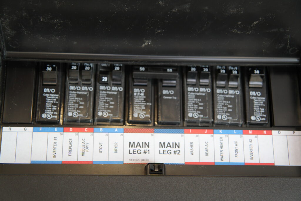
A 50 amp split-phase breaker panel
A 50 amp service will be different because it’s a two pole split phase service with two hot wires. In this case the black wire will be referred to as L1 while the second hot phase will be a red wire and referred to as L2. In this instance the breaker panel will have two main lug inputs and a divided buss that sends L1 to half of the breakers while sending L2 to the other half. In either situation there will be a main breaker that controls power to the entire distribution panel. It will either be a single pole 30 amp breaker or a two pole 50 amp breaker, depending upon which service your motorhome is equipped with.
In addition to the main breaker there will be a number of output breakers – one for each circuit in the coach. Any given circuit may contain multiple outlets, but that particular breaker will control every outlet on its circuit. So if a device that is plugged into an outlet causes the circuit breaker to trip, that entire circuit will be dead. Some of the panels used in motorhomes are fairly small so that they don’t take up too much room, which is somewhat limited in an RV. However, there may not be enough available slots for the number of circuits that are needed. Split circuit breakers are commonly used in this application to solve this problem. A split breaker places two half width breakers into one common unit that snaps into a single breaker panel slot. This gives you the ability to run twice as many circuits as normal circuit breakers. Of course, you still need to find enough room inside the box to stuff all of that wire so that may be the limiting factor.
Sub-Panels
Normally, all of the circuits can be powered from the one breaker panel. Many motorhomes are now coming with more complex electrical systems and are using inverters to power certain devices. We’ll talk more about inverters in a later chapter, but for now let’s just say that inverters use battery power to produce 120 volt AC power. Inverters are also fed 120 volt AC power from the breaker panel. They have an internal transfer switch that passes the shore power through rather than using the batteries to produce power. It will pass this power through whenever it is available or invert it from the batteries when it is not. This means that any devices that need to be powered from the inverter need to somehow be connected to its output. They still require some sort of overload protection so many of the larger inverters send their output, or the pass through power, to a sub-panel. This sub-panel will act as a distribution point for all of the circuits that are desired to be run off the inverter. It will have a few circuit breakers in it to protect these circuits from any overloads. The inverter itself will receive power from either one or two circuit breakers in the main panel. In this way all of the AC power from the main breaker panel will pass through the inverter and into the sub-panel, where it can be distributed to the desired circuits. Many of the larger inverters also serve as battery chargers, so whenever shore power or generator power is present it will charge the batteries in addition to operating in the pass-through mode.

Iota integrated breaker panel
This requires the installation of a second panel. Adding a sub-panel to an RV does take up valuable space, which isn’t always that easy to do. Some breaker panels, such as the Iota IDP-240B, offer an integral sub-panel. By splitting the buss inside the panel, a portion of that box can be used for sub-panel circuits if the inverter is wired to return power to that portion of the buss bars. This offers a huge advantage when trying to fit a breaker panel into an RV without tying up valuable space. The Iota is a compact breaker panel with an attractive cover with a smoked glass cover over the breakers. If a breaker trips, an LED can be configured to illuminate, which identifies the circuit as tripped without requiring removal of the cover. It can be configured with the split buss design so a separate inverter fed sub-panel is not necessary.
Batteries and Chargers
Batteries are critical to an RV. They start the engine and provide power to run accessories when driving. When parked they provide power to run lighting, water pumps, and various other 12 volt accessories. They can even be used to power an inverter to provide 120 volt AC power. Because of their heavy use they can sometimes be a source of aggravation and maintenance. Let’s take a closer look at batteries, how they work, and how to properly care for them. We’ll also delve into battery chargers and charging methods.
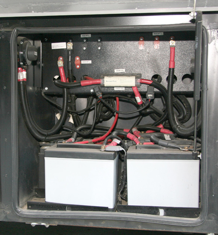
The battery compartment from an Allegro Bus
A single battery may be fine to operate your passenger car but it’s just not enough power to handle the more advanced requirement of an RV. To do this, multiple batteries are arranged together into a battery bank. There are two types of batteries and each type has a different intended use. Automotive batteries are what you have in your car. They are designed to output a large burst of amperage to start the vehicle, then slowly recharge from the vehicle’s alternator. The key here is that they dump a lot of amperage in a short time, then rest for a while slowly getting recharged. Most diesel motorhomes will have two engine-starting or chassis batteries in order to crank these larger engines.
When camping, your coach electrical systems operate quite differently. They will draw fewer amps than a starter motor but they will do that over a longer period of time. For this application deep cycle batteries are used. Deep cycle batteries are designed for maximum performance by slowly draining amps from them and sustaining this draw over a longer period of time. Most coaches will have four deep cycle batteries in a battery bank to ensure that there is enough capacity to supply adequate power over a longer length of time. This can vary and some smaller coaches may only have two, while larger coaches may have as many as eight batteries in a bank.
RV electrical systems are 12 volt systems. Whenever you connect multiple batteries together you have to make the proper connections in order to maintain 12 volts. If batteries are connected in parallel they will retain their voltage, but if they are connected in series the voltages will add up. So, if you have a bunch of 12 volt batteries that you want to connect into a battery bank, you simply connect all of the positive and negative posts together to give you increased load capacity or amp-hours. But many RVs are using 6 volt batteries for their deep cycler applications, which are commonly used in golf cart applications. They have a heavier plate design and are more durable, plus they output more power than a 12 volt battery of similar dimensions. The only downside is that you need to connect them properly to get a 12 volt output. Basically, you connect a pair of 6 volt batteries together in series to give you a single 12 volt battery. Then you connect the positive posts of this pair together with all of the other pairs and then do the same with the negatives. The following diagrams show a four battery bank of both 12 volt and 6 volt batteries and will help explain this better.
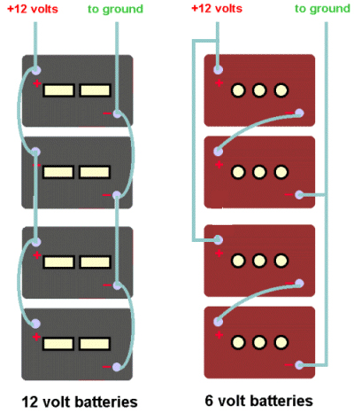
diagram of series versus parallel battery connections
Battery Types
Batteries come in different types. For RV applications the most common are flooded batteries or AGM batteries. Flooded batteries are filled with electrolyte. This electrolyte is a diluted form of sulfuric acid. When a load is placed on the battery, the acid puts a charge on the lead plates and creates electricity. At this time some of the sulfur and oxygen leaves the acid and forms a sulfate on the lead battery plates, leaving water as the remainder. If a battery is totally discharged, the battery plates will be coated with sulfate and the electrolyte will be mostly water, which is why dead batteries can freeze in cold temperatures but fully charged batteries will not freeze. When the battery is recharged, the sulfate falls of the battery plates and recombines with the water to change it back to acid again. If the battery is overcharged (in other words excess voltage is applied to it when it already is charged up), the water can boil out of the battery and acidic vapors can leave via the vented battery caps. This reduces the water level and if it gets below the battery plates it can harm the battery. It also tends to corrode the battery connections because of the acidic vapors. Maintaining the proper water level is critical to good battery performance.
AGM batteries use electrolyte but not in a liquid form like flooded batteries. The acidic electrolyte is absorbed into glass fiber mats that are wrapped around the lead battery plates. With AGM batteries there is no need to ever worry about adding water because there is no water in them so maintenance is greatly reduced. The battery terminals also are not as susceptible to corrosion as flooded batteries because there is only microscopic outgassing, or venting, of electrolyte vapors. The outgassing of flooded batteries means they need to be in a vented compartment and clear of anything that could create a spark. AGM batteries can be located anywhere because they truly are sealed. AGM batteries are typically used in aircraft and they can be used in any orientation, even upside down, with no negative consequences. AGM batteries also offer greater performance over a comparable flooded battery because the voltage drop curve is flatter.
| Voltage | State of Charge |
| 12.6+ | 100% |
| 12.5 | 90% |
| 12.42 | 80% |
| 12.32 | 70% |
| 12.20 | 60% |
| 12.06 | 50% |
| 11.9 | 40% |
| 11.75 | 30% |
| 11.58 | 20% |
| 11.31 | 10% |
| 10.5 | 0% |
Battery Charge Voltages
A fully charged battery will test out at 12.6 volts. This is “at rest” voltage. When a battery is being charged, the alternator or battery charger will put out higher voltage, sometimes as high as 14.5 volts. Immediately after stopping the engine or switching off the battery charger, the battery will have a false surface charge which is meaningless and probably in the mid-13 volt range. Leave it rest for a while (at least 15 minutes or as long as an hour or two) before testing. This will allow the battery to rest and lose its surface charge. A slight load will help shorten that time somewhat. You can continue to draw current from the battery until the at-rest voltage drops below 11.9 volts. At that point only 40% of the battery capacity remains. In other words, you’ve used 60 amps from a 100 amp battery. If you continue to use the battery below this point you can get current from it, but the voltage will be low and that won’t do your electrical equipment any favors. You will also drastically shorten the battery’s life.
Batteries are not really rated in years of life. A battery is typically rated at 50 cycles of discharge and recharge. In other words you can totally discharge the battery, then recharge it. That’s one cycle. Do that 50 times and the battery will be shot. The level at which you discharge isn’t linear, it’s graded on a curve. So, if you only drain the battery halfway and then recharge it you won’t double your life to 100 cycles. It’s more like 200 or more. Similarly, if you only drain your battery to 75% you won’t quadruple your battery’s lifetime to 400 cycles. It’s more like 1,200 cycles. It is to your advantage to keep your battery bank from getting too low by frequently recharging it.
If you were to plot battery voltage vertically on a graph against battery consumption horizontally on that graph, you would see that the voltage doesn’t drop off in a straight line. It falls off on a curve, which drops fairly rapidly at the halfway point. This helps explain why the old rule of thumb is to not discharge your batteries below 50%. So, a 220 amp-hr battery is safely capable of giving up 110 amp-hrs without risking any damage to that battery. AGM batteries have less internal resistance than flooded batteries. This means that they can take a charge faster than flooded batteries but it also means that their voltage drop graph will be much flatter than a flooded battery. By the time you reach that 11.9 volt level you have given up many more amp-hrs than you would with a flooded battery. Typically, an AGM battery can give up 30% more amp-hrs than a flooded battery, so you can get 140 amp-hrs from a 220 amp-hr battery instead of the 110 amp-hrs that you would be able to get from a flooded battery. In effect, you are getting some free usable battery capacity from an equal sized battery bank.
Battery Testing
Battery testing tends to be confusing for some. Part of the reason is that there are three tests that one can perform on batteries and not one of them will give you the total picture. You need to understand what these testing devices will do and how to interpret that information. To do this we’ll look at voltmeters, hydrometers, refractometers, and carbon pile testers.

Array of battery measuring devices
The voltmeter is the first thing that anyone goes for. It’ll tell you just how many volts the battery has in it. If this is performed on a battery that has been resting, we can use the above chart to determine if it is fully charged or not. However, it’s not the ultimate tool because it won’t give you any indication as to the ability of the battery to deliver electricity under load. It could just be a surface charge that will fall flat when a load is applied. If your battery has a bad cell the voltmeter won’t give you an accurate reading of how good your battery is. Remember that the electrolyte in each cell changes between acid and water depending on the charge level. To check each cell, we need to take a sample of the battery fluid and test it for specific gravity because acid is heavier than water. If we use a hydrometer we can extract a sample of the electrolyte and test its specific gravity. A fully charged battery cell will have a specific gravity of 1.277 at 80F. As the charge level decreases, so will the specific gravity. The following table shows the various charge levels, at rest voltages, and specific gravity. By testing each cell we can test to see if one bad cell is causing the battery to fail. If one cell is bad, then the battery will need to be replaced. An even better way to test for specific gravity is to use a refractometer. You simply place a drop of fluid onto the refractometer, aim it at a source of light, and look into the eyepiece. The display will show you exactly what the specific gravity is and is temperature compensated, whereas when using a hydrometer you will need to apply temperature correction tables to the float reading. Refractometers also have another benefit in that the same unit can also be used to test antifreeze protection levels.
| Percentage of Charge | Specific Gravity Corrected to 80o F | At Rest Voltage |
| 100 | 1.277 | 12.73 |
| 90 | 1.258 | 12.62 |
| 80 | 1.238 | 12.5 |
| 70 | 1.217 | 12.37 |
| 60 | 1.195 | 12.24 |
| 50 | 1.172 | 12.1 |
| 40 | 1.148 | 11.96 |
| 30 | 1.124 | 11.81 |
| 20 | 1.098 | 11.66 |
| 10 | 1.073 | 11.51 |
All of the above in formation serves to inform you of the battery’s state of charge. It has no bearing whatsoever on the ability of the battery to produce any volume of power, although you first need to know that the battery is charged up before continuing with further testing and it will point out any failed cells within the battery. To determine its output capability, you will need to perform a load test. The best tool for deep cycle batteries is a carbon pile tester. A carbon pile tester consists of a carbon pile rheostat. As you dial the knob in, it increases resistance and simulates a load on the battery. It’s bigger than a light bulb but smaller than a dead short, so think of it as a controlled short that will suck power from your battery. The tester also includes a voltmeter and ammeter. You simply connect the alligator clips to the battery terminals and dial in the knob on the tester. The display on the ammeter will indicate the load increase. For deep cycle batteries, you dial it in until the ammeter reads two times the rated battery current, so a 100 amp-hr battery would get turned down to a 200 amp draw. For chassis batteries you dial it in to 50% of the CCA rating of the battery. You then check the voltmeter to see if the voltage holds in the green zone. If it drops down into the red zone, your battery is not capable of sustaining that output level and will need to be replaced. At the same time, you can inspect the battery cells to check for any boiling or bad cells if you want to know why your battery failed. Voltmeters and hydrometers alone will not give you this information. You need the variable load of the carbon pile tester to accurately test this.
Battery Care and Maintenance
To ensure that your batteries perform their best and last the longest you will need to take care of them. Batteries can’t pass power to the electrical system if their connections are all corroded. The acidic electrolyte in flooded batteries tends to eat away at the copper and lead connections and eventually corrosion will build up and hamper the flow of current. You will need to check and clean these connections regularly as part of a scheduled maintenance cycle. Flooded batteries can lose water over time and it’s important to check your water levels so that they do not get so low as to expose the battery plates. Keeping the batteries away from very hot locations will help in this but the biggest cause of battery water evaporation is due to overcharging. Putting excess voltage into a battery that is nearly charged will boil the electrolyte and the battery will outgas. If you find that you are repeatedly adding water to your batteries, it’s time to check your charger’s float voltage.
Battery Chargers
We all know how easy it is to take power out of a battery. What about recharging them when they are low? Batteries in a motorhome can be charged in a number of ways depending on the current mode of operation and whether they are chassis batteries or coach batteries. First off, we need to understand that there are two separate battery banks on a motorhome – the chassis batteries and the coach batteries. The chassis batteries are for starting the motorhome’s engine and powering the headlights, wipers, and other chassis related accessories. When driving down the road the vehicles alternator will charge the chassis batteries. The “house” portion of the motorhome has a separate bank of batteries called the coach batteries. These are deep cycle batteries that will power the lights, domestic water pump, fans, and any other accessories that are related to living in the coach while parked. These batteries are kept separate from the chassis batteries so, in the event that you run them down too low, you will still be able to start the motorhome’s engine. A Charge Solenoid is installed to connect both the chassis and battery banks together. This solenoid is engaged whenever the ignition key switch is in the “on” position. The engine can then recharge both battery banks when driving down the road. As soon as you are parked the solenoid opens and the two battery banks are divorced once again.
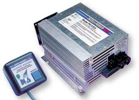
Convertor
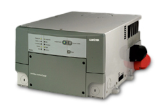
Xantrex inverter/charger
But, what about when we are parked at a campsite? We don’t want to have to run the engine all the time to recharge these batteries, so we need other options. The first option is a battery charger that is dedicated to the coach’s electrical system. This charger is a 120 volt device that will be powered whenever we plug into shore power or run our generator set. In addition to charging the batteries we also need to provide clean power with consistent voltage to power the 12 volt electrical components while we are parked rather than use the batteries to power them. This device is called a converter. The converter is hard-wired into the 120 volt electrical system as well as the 12 volt system. It “converts” 120 VAC power to 12 VDC power to run the 12 volt accessories as well as charge the coach battery bank. So, now we have the ability to recharge the coach batteries via the engine alternator when driving or via the converter when parked with shore power or when running the generator. When boondocking we can use the batteries to provide power. When the voltage gets to that magic 50% mark, we can fire up the generator set for an hour or two to power the converter and recharge the batteries. The actual charge time will vary according to the size of the converter as well as the size of the battery bank. If the battery bank is 440 amp-hrs and it is at 50% you’ll need 220 amp-hrs to bring it to its fully charged state. If you have a 60 amp converter you’ll be looking at close to 4 hours to output that much power. Larger converters take less time but cost more.
Another popular device is the inverter. An inverter does just the opposite of a converter. It creates 120 VAC power from 12 VDC. It is used to power 120 volt devices via battery power so that you don’t have to run the generator all the time. Small inverters run from 250 watts up to 1,000 watts and are installed into an electrical circuit. No battery charging capabilities exist on a basic inverter so most diesel pushers use an inverter/charger unit. These units combine the features from both an inverter and a converter. They are generally found in larger sizes, such as 2,000 watt and 3,000 watt. These inverters are connected to a dedicated 120 volt circuit breaker in the main breaker panel and also connect to the coach batteries via large diameter battery cables. They feature an automatic transfer switch that will pass shore power through when present, or switch over to battery fed inverter power whenever shore power is not present. Note that the running the generator is the same thing as shore power in this instance. Whenever 120 VAC power is present the inverter not only passes that power through to the electrical devices fed by it, but it also acts as a converter and provides 12 volt current to power the house accessories and recharge the coach battery bank. Typical inverter/chargers have battery charging capacity in the 100 to 140 amp-hr range so they are larger and faster than a converter. When an inverter/charger is present there is no need for a converter.
Both converters and inverter/chargers feature three battery charging modes. When a battery is low on charge the first mode is the bulk mode. This mode provides full charging output to the batteries. As the battery approaches the full mark the charger will kick into absorption mode. In this mode the voltage is regulated to not be excessive so that the batteries can absorb this charge without boiling. Finally, in order to maintain a charge in a battery that is very close to full the float mode will be engaged. In this mode charger output voltage will be limited to no more than 13.2 volts so that excess outgassing does not occur. You can safely leave your batteries connected to the charger indefinitely if it’s in float mode without fear of boiling out water. Of course, this assumes that your charger’s float mode is functioning properly. If you are adding water frequently it’s time to have your charger’s float voltage checked.
Equalizing Batteries
We talked earlier about how battery electrolyte loses its acid content and turns to water and deposits sulfate on the battery plates as it is discharged during normal operation. We also mentioned how this sulfate “falls off” the battery plates and recombines with the electrolyte as the battery is recharged. But this process isn’t perfect and some of the sulfate will remain on the battery plates. The more we use the battery, the more sulfate remains on the plates. Each time that the sulfate remains on the plates we lose some battery capacity. If it continues we have a sulfated battery that just isn’t capable of giving us the performance that it was originally designed for. If we wait until it’s really serious the battery will need to be replaced. However, it is possible to clean some of this sulfate off of the plates if we don’t wait until it’s too far gone. This can be done by a process called equalization. When we equalize batteries we apply excessive voltage to that battery, or battery bank. This excess voltage will boil the electrolyte and cook the sulfate off so that it can recombine with the electrolyte, restoring both the electrolyte and battery plates to their original condition. This process isn’t 100% perfect either, but it will greatly extend your battery’s life and improve its performance if done regularly. The time frame between equalizing batteries will vary as to how you use your batteries. If you frequently run them low and recharge them, you’ll need to do this more frequently than if you are plugged into shore power most of the time and don’t demand those deep swings in charge level. If you use them hard, equalizing every 6 months would be a good idea, otherwise once a year should be sufficient.
Equalizing requires a period of time where you will put high voltage into your battery bank. Most converters and inverter/chargers have the ability to perform an equalizing procedure on your batteries. Refer to your owner’s manuals for the exact technique used to initiate an equalizing charge with your particular charger. When equalizing the charger will output around 15.5 volts. This is too much for your coach’s electrical devices to handle so it’s important to disconnect any loads in the coach during this time. Operating the battery disconnect solenoid switch will kill most power to the coach, but there may be a few devices that are connected directly to the batteries and are not run through the disconnect solenoid. Check for these and pull fuses or whatever else it takes to disconnect them. Note that it is not necessary to disconnect the chassis system because you will only be equalizing the coach batteries. Chassis batteries do not require equalizing because they are not deep cycle batteries or subject to those conditions. Also, equalizing is only to be done on flooded batteries. If you have AGM batteries equalizing is not needed, nor should it ever be performed on AGMs or they will be damaged by the equalization process.
That’s it for this month. Be sure to check out next month’s final installment that covers low voltage circuits, inverters, automatic generator start systems, solar power, energy management systems, and surge suppression.

Mark Quasius is the founder of RVtechMag.com, the past Midwest editor of RV Magazine, writes for numerous RV-related publications and a regular Contributor to FMCA’s Family RVing Magazine. Mark and his wife Leann travel in their 2016 Entegra Cornerstone.

