
Understanding the basics of RV electrical systems is important to every RV owner. The electrical system of a motorhome can be quite complex, involving 12 volt DC battery power as well as 120 volt AC power. It’s unavoidable that issues will occur from time to time but many of these can easily be corrected by the RV owner with a basic understanding of electricity. Without this knowledge it can be a daunting task to track down and correct any electrical issues but knowledge is power (pun intended) so this tutorial will help you to better understand how your motorhome functions by teaching you the basics of electricity and how to apply that to your motorhome.
This information is a bit much to cram into one installment so this month’s article will be part one of a three part installment. This month we’ll cover the basics of electricity itself as well as how your breaker panel is wired. Some of this stuff might be a bit of a yawner but we first need to learn some of the basics before we get into how to wire the space shuttle. Next month we’ll make it more interesting as we move on to batteries, generators, transfer switches, inverters and other electrical components. The third and final installment will cover more advanced components such as solar power, surge protection and energy management systems. At the conclusion of this series you’ll have a better understanding of your motor coach’s electrical systems and be capable of handling minor repairs on your own or knowing when to take it to a service center for professional help so be sure to mark your calendar and tune in for the whole story.
What is Electricity?
In short, electricity is energy. You can’t really see it, which can make it a bit harder to understand, but you can see the effects of it in operation. Stick your finger in a lighting socket and you’ll know what I mean. It may help to think of it in the same manner as a fresh water system. Your water system has pressure, measured in PSI (Pounds per Square Inch), and volume, measured as GPM (Gallons P{er Minute). Electricity also has pressure, which is expressed as voltage, and volume, which is expressed as amperage. In order to run a sprinkler you need a certain PSI and flow rate (GPM) to make it function. In order to run an electrical component, such as a motor or lighting fixture, you need a certain voltage and amperage to allow it to operate. As the flow rate of water increases you’ll need a large diameter pipe to handle the increased water flow. As the amperage in an electrical circuit increases you’ll need a large wire gauge to handle the increased amperage so once again we can see similarities between the two systems.
To make a light bulb burn or an electrical motor work we need to pass it some electrons. As these electrons move through our device, commonly referred to as an electrical load, the energy from these electrons will cause that device to do whatever it was designed to do – light up, make toast, or motorize something. To simplify this think of an electron as giving a “high five” to the light bulb every time it passes by. Each time it does that the bulb lights up for a brief instant. Now, line up a whole bunch of electrons in a row and pass them all by the light bulb giving a series of “high fives”. Now you have a light bulb that stays lit until someone shuts off the switch and stops the parade of electrons past the light bulb. In a nutshell, this is how electricity works. It works in the same manner for light bulbs, heating elements, magnets, motors, etc. But to keep it simple I’m going to simply refer to light my bulb illustrations in this tutorial.
Now that we see that electrons passing through the bulb causes it to light up the next thing we need to understand is that this electron doesn’t die after it passes through. It still retains its energy so it can be used over and over. That’s the reason why you can string a chain of light bulbs together in a row and they’ll all light up. The electrons don’t wear out. But in order to make electrons move we need to create a path for them to follow. This can’t be a dead end. Let’s go back to the “water” analogy for a minute to help illustrate this. Let’s assume that we have a pool of water with a submersible water pump located in the middle of the pool. We attach a hose to it and turn on the pump. The water flows out the open hose and returns to the pond. We now have a fountain
But, if we cap off the hose and turn on the pump, nothing comes out. We have no water flow and our fountain no longer works. The same thing holds true for electricity. If we take a battery and connect a wire from one terminal to a switch, and then to the first terminal of a light bulb we basically have the same thing as the capped off hose. The electrons have no place to go so our light bulb doesn’t light up. When we attach another wire to the light bulb’s second terminal and connect it to the other post on the battery we now have a complete circuit because the electrons now have a complete path to follow and can comfortably parade around in a circle, causing the light bulb to remain illuminated as long as we don’t open the circuit by removing the wire or opening the switch. When a circuit is complete it is commonly referred to as a closed circuit. If we open a switch or break the loop somehow, as in a bad connection, it is considered an open circuit and nothing will be powered up.
Because electrons don’t die after passing through a device, they can be used over and over. You just have to keep them moving. In the case of the battery they simply return to the battery by following the closed circuit, or loop. But there are two kinds of electricity – Alternating Current, commonly referred to as AC, or Direct Current, commonly referred to as DC. In the above example of our battery, we were using DC current because DC current is what batteries produce. In DC, we send the electrons down a wire and then return them to the battery. They always go in the same direction – out one way and back the other which is determined by polarity.
Polarity is like a magnet, which has a north and south pole. The lines of magnetic force flow from one end to the other and always in the same direction. Technically electrons flow from negative to positive, which can be confusing because 99% of the automotive electrical systems currently (no pun intended) in use connect the power leads to the battery’s positive terminal then onto the light bulbs and accessories and then to the vehicle’s frame as a ground, which is connected to the battery’s negative terminal to complete the loop. The advantage of using the frame as a ground is that you don’t need to run dozens of ground wires back to the battery to complete the circuit. You use short jumper leads to the frame and then the vehicle’s frame carries the current back to the battery, as long as the frame is made of a conductive metal to conduct the electricity. Because the battery’s negative terminal is connected to the frame ground, the battery current actually flows to the frame first, then to the light bulb, then to the switch, then to the fuse, and finally to the battery’s positive (hot) terminal. But, it really doesn’t matter which direction the electrons flow as long as they flow. So, just to make this easy to understand we are going to talk about electricity as if it flows from positive to negative. For a quick history lesson – many of the older vehicles did have a 6 volt positive ground system until 12 volt negative ground systems replaced them in the 1950s.
AC Versus DC:
Battery powered circuits will always be DC as were the very first generators. A battery always has a steady “push” of current. If you were to look at it on an oscilloscope you would be seeing a straight line extending across the screen someplace above the center line. The actual height of this line will vary according to what the voltage is. A DC generator isn’t the same though. Because you have an armature rotating inside a housing with two field magnets you have a pulse every time the armature coil passes a field coil and a dead spot when it’s in between field coils. On an oscilloscope this looks very much like a bunch of waves on the top of the ocean with gaps in between. DC current isn’t all that efficient which is why the automotive industry dropped DC generators in the early 1960s and went with alternators to deliver more power. An alternator produces AC current and then uses diodes to rectify that into DC current. Let’s look at a waveform comparison of both AC and DC current to help understand the differences.
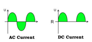
Waveform comparison of both AC and DC
In the above illustration we have the AC waveform on the left and the DC waveform on the right. Voltage is plotted vertically and identified as “U” on the graph so the higher the waveform, the greater the voltage. Time is plotted horizontally and identified as “R” on the graph. We can see a large gap between the two “humps” on the DC graph. That’s when the armature is in between the field coils and the generator isn’t producing any power. This is a characteristic of a DC generator. The graph on the left shows an AC waveform. In this case positive polarity is above the center line while negative polarity is below the center line. You get twice the power pulses, or “humps”, in an alternator as in a DC generator by eliminating those gaps between the humps. Adding built-in diodes to an alternator will rectify this current into DC current so that it can supply power to recharge the battery. The result is that an alternator is capable of higher outputs than a DC generator, especially at low RPMs, such as during engine idle time. In the case of 120 volt high voltage systems the devices are all designed to run on AC power so there is no need to rectify this current to DC. The only reason we still need to convert AC to DC in an automotive application is because you cannot mix AC and DC current. Automotive applications rely on a battery to provide power to crank the engine, provide extra reserve capacity when the alternator isn’t quite enough to meet temporary high demands, and to power accessories when the engine is not running.
We mentioned the word “polarity” earlier. Polarity refers to whether or not a pole is positive or negative. We learned earlier that electrons flow from negative to positive so on a DC circuit they always flow in the same direction. A true AC circuit, such as a 120 volt AC circuit, has polarity that constantly shifts, or alternates. That’s why it’s called “Alternating Current”. Remember the earlier analogy of the parade of electrons passing by and giving a series of “high fives” to the light bulb in the DC circuit? In an AC circuit the electrons are constantly changing (alternating) direction. It’s as if they take one step, turn around and come back one step, then turn around and take that same first step over again – and repeat this little dance forever as if they really can’t make up their mind, sort of like a squirrel crossing the street in front of a vehicle. However, these electrons don’t die once used so as long as an electron passes by the light bulb, it will light up. With AC current it’s the same electron, rather than a parade, but it’s just dancing back and forth underneath the same light bulb filament. All the other electrons just act as a push-pull chorus line directing the movement of that electron. Therefore polarity really doesn’t exist in an AC circuit, unlike in a DC circuit, because it’s constant changing. You still need to have a complete circuit, just as in a DC circuit, but there is no positive or negative labeling involved. In a DC circuit the positive terminal is typically referred to as “hot” while the negative is called “ground”. In an AC circuit it’s still advantageous to refer to the wires by names so these terms are replaced by “hot” and “neutral” because there is no polarity and the higher voltages present require insulated return lines rather than a frame grounding return.
Amps, Volts and Watts:
Voltage is the force or pressure exerted upon the electrons to get them moving. As the voltage increases, so does the ability to make power. Low voltage doesn’t have very much force, which is why you can touch a small 9 volt battery with your finger and not even feel it. Touch it to your tongue however and you’ll know whether or not it’s dead because the current will flow through the saliva on your tongue, completing the circuit more easily than on your dry finger. Up that voltage to 120 volts and you’ll be the one that’s dead rather than any battery. Higher voltage is necessary to overcome the resistance in the conductor. Conductors such as copper wire are a great choice for wiring due to its low resistance and is commonly used in electrical circuits.
Wire is used to conduct electricity to where it is supposed to go but in order to contain that electricity inside the wire it needs to be insulated. The insulation needs to be capable of preventing any short circuits between the inner conductor and anything that it passes nearby. As the voltage increases, the quality of the insulation also needs to increase. Automotive wire is commonly called low voltage wire because it’s good for handling 12 to 24 volts but it won’t contain a higher 120 volt current. High voltage wire, as used in residential construction, is available in two versions. The full version is rated at 600 volts while the junior version is rated at 300 volts. Either will work for a 120 to 240 volt AC circuit but the 600 volt wire has a thicker insulation capable of containing a higher level of voltage than the junior version. High voltage wire can be used in a low voltage situation but low voltage wire can never be used in a high voltage situation.
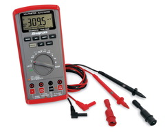
Voltmeter
Voltage is measured by a voltmeter, which can be a dedicated unit mounted in a panel or a hand-held multi-meter. Voltmeters that are mounted in an RV are a single function display while the vast majority of portable test equipment is found in the form of a multi-meter, which combines voltage with other measurements, such as amperage, resistance, etc. This popular item is really something that every RV owner should have in their toolbox because it can be useful in many different situations.
Whereas voltage represents how hard the “push” is upon the flow of electrons, amperage represents the actual volume, or “quantity”, of electrons in that flow. This is measured by an ammeter that can either be mounted into an RV control panel or it may be part of a portable multi-meter. Amperage is current flow and just like water flow, it needs an adequate sized conductor or “pipe” to flow through. The larger the flow, the larger the pipe diameter needs to be. Wire is measured in Wire Gauge sizes, sometimes referred to as American Wire Gauge (AWG) when sizes are given. The wire diameter gets smaller as the number gets larger, so a #16 wire is smaller in diameter than a #12. When you get to large diameter cables, such as used for batteries or welders, you’ll eventually run out of numbers at zero. At that point you start doubling digits so a #00 cable is larger than a #0 cable but smaller than a #0000 cable. After that it gets more complex but we don’t need to go there because RVs don’t have that large of wiring and #0000 is as large as you’ll ever see.
Wire gauge size has nothing to do with voltage. All it’s concerned with is the amperage, or current flow. But, as we previously mentioned, the insulation value is voltage sensitive. This means that a #0 battery cable designed for 12 volts will not have sufficient insulation to contain a 120 or 240 volt current so it is not to be used for high voltage applications. Both a high voltage and low voltage cable of the same diameter will be able to safely pass the same amperage but not the same voltage.
Now that we know what voltage is and what amperage is we now need to see what the relationship is between them and why we just don’t have one voltage to run everything so as to keep it simple. That’s where wattage comes in. Wattage is the result of multiplying amps times volts. In other words a light bulb that consumes 5 amps at 12 volts is a 60 watt light bulb, because 5 times 12 equals 60. Wattage is considered True Power and that’s the part that is important because it’s wattage that performs the work, not amperage or voltage. Let’s look at a high voltage application as an example.
We’ll assume that there is a device, such as a shop air compressor with an electric motor that needs 3,600 watts of power to operate. If we want to plug this into a 120 volt wall outlet we will first need to find out how big of a circuit we need to run it. We know that amps times volts equal watts therefore watts divided by volts will give us amps. By dividing 3,600 watts by 120 volts we see that we will need a 30 amp circuit to run this unit. The typical duplex receptacle uses a #12 wire with a 20 amp circuit breaker so that’s not going to happen because the circuit breaker will trip whenever the compressor is turned on. We either need to supply it with a larger #10 wire outlet and 30 amp breaker or change the parameters of our equation. We can do this by changing the voltage. If this motor happens to be a dual voltage motor we can rewire the air compressor’s motor so that it runs on 240 volts, which will reduce the amperage running through the compressor. Using our formula once again we can divide 3,600 watts by 240 volts and we now see that we only need a 15 amp circuit, because 3,600 divided by 240 equals 15. By doubling the voltage we’ve effectively cut the amperage in half. Remember that the motor doesn’t need amperage to run. It needs wattage to operate.
Another benefit to increasing the voltage and reducing the amperage is that we can reduce the wire gauge size down from a #10 wire to a #14 wire because the wire gauge is not interested in voltage, only amperage. This is the reason why utility companies move huge amounts of current through 40,000 volt wires and then step it down to a more useable voltage via transformers and sub-stations. If they ran everything through at 120 volts the wire diameters would probably be the size of a freight train. Yet high voltage requires serious insulation, which is why those huge glass insulators are used on utility poles. Those just aren’t practical for wiring inside an RV so lower voltage insulated wires are used to make the system more manageable.
If you are or were a Trekkie you may recall hearing the Borg saying “Resistance is futile”. But that doesn’t apply to electrical systems because resistance in an electrical circuit plays into every situation when dealing with electricity. We can measure resistance with an ohmmeter or calculate it with a simple equation.
The most commonly used formula in basic electricity is called Ohm’s Law, which is named after the German physicist Georg Ohm. It simply states that E = I * R, or Voltage (E) equals Amperage (I) times Resistance (R). Resistance is just a measurement of how hard it is to pass electricity through something. It’s measured via an Ohmmeter or multi-meter and expressed in Ohms. A 2×4 hunk of wood has extremely high resistance so wood does not make a very good conductor of electricity. Silver is the best but for obvious reasons (cost) it doesn’t get used very often except in computer processors. Copper is the most popular conductor and the majority of the wiring out there will be copper because it has low resistance and is more affordable than silver. If we add a tungsten or nichrome wire to our circuit, it will have higher resistance but it will still conduct electricity. As current passes through a tungsten wire that resistance will cause it that wire to glow if it is kept in a vacuum or surrounded by an inert gas therefore it will make a good light bulb filament. Nichrome is commonly used as a heating element, such as in a toaster.
You will have less light or heat output as the resistance increases. For example, a 60 watt light bulb running on a 120 volt circuit consumes 0.5 amps (60 watts / 120 volts = 0.5 amps). Using Ohm’s law we see that the resistance equals voltage divided by current (amperage) so our light bulb has 240 ohms of resistance (120 volts / .5 amps = 240 ohms). If we look at a brighter 150 watt bulb we see that it needs 1.25 amps to run (150 watts / 120 volts = 1.25 amps). Using Ohm’s law we get 96 ohms as the resistance (120 volts / 1.25 amps = 96 ohms). This shows us that we get more light (wattage) out of a higher flowing filament with less resistance than with a high resistance lower flowing filament. That’s also the reason why brighter light bulbs don’t last as long as those of lower wattage. Their thin filaments that give them greater illumination aren’t as durable.
This formula can also be used for testing other components. You can use these formulas to determine if an electric heating element, such as a hot water heater, is functioning as it should. Simply find the wattage of the water heater and divide that figure by its voltage to get its amperage rating. Then take the voltage, divide it by the amperage to get what the resistance of the water heater element should be. Then test the element with an ohmmeter to see what it reads. It should be reasonably close to your calculations. If not, your element isn’t heating as it should and probably needs to be replaced.
Resistance also affects voltage. The AC components in your RV are designed to operate on 120 volts. There is some tolerance, plus or minus 10%, but if the voltage goes higher or lower than that you can damage your equipment. If you run too much current through too small of a wire or cord, the voltage drops. Using Ohm’s law we can understand why. Let’s assume we have a 100′ long #12 gauge cord which has a resistance of 6 ohms. This is capable of passing 20 amps of current at 120 volts (120 volts / 6 ohms = 20 amps). When we try to pass 30 amps of power through this cord, which is only rated for 20 amps, we get a voltage drop because the extra current cannot overcome the resistance. We would need a larger #10 gauge cord with 4 ohms of resistance in order to pass 30 amps of power. If we try to pass 30 amps through the smaller cord the voltage will drop and the amperage will rise. This will cause the cord to heat up, possibly starting a fire. For this reason circuit breakers must always be sized for the proper size wire gauge and never replace with a larger breaker than that wire can safely handle.
Are you bored yet? Now we’ll start getting into a bit more information specific to an RV.
Split Phase:
Most larger motorhomes now come with a 50 amp service while older motorhomes came with 30 amp services, as do many of the smaller towable RVs. Over the years a lot of amenities have been added to motorhomes. As washer-driers, multiple air conditioners, larger refrigerators and other large accessories are added the power requirements also increase. But not every RV park has upgraded their electric supply to accommodate today’s electrical demands. Sometimes certain areas are set aside with 50 amp service while others still have 30 while some parks have upgraded their power grid properly. Because there needs to be compatibility with all RVs a multi-outlet pedestal is usually installed that will supply a 50 amp service, a 30 amp service, and even a 20 amp duplex receptacle for the smallest power requirements. A cutaway image of a typical power pedestal is shown below.
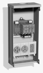
Power Pedestal
In the above pedestal image we can see three separate outlets. From left to right they are 50 amp, 30 amp, and 20 amp. Each receptacle has its own dedicated breaker sized for that particular outlet. This gives the RV owner the choice of choosing whichever outlet they need to best match their RV’s electrical service. But, before we delve into the available services we first need to understand what a split-phase service is.
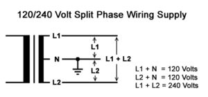
When you create electrical power there is always a pair of windings in the generator that power is taken from. This is true whether it’s a small portable generator, a large diesel powered RV generator, or a huge megawatt generator at your local power utility. These two windings are connected together in series and a tap is run into their common center connection. In the above diagram we can see that the ends of these windings are identified as L1 and L2. The common center tap of these two windings is identified as N while L1 and L2 are the hot leads brought into your breaker panel at home and each is generally referred to as a “phase”. The N is the Neutral wire that goes to the neutral buss connection in your breaker panel. This is exactly the same way that your RV’s breaker panel is configured. If you put a voltmeter across lines L1 and L2 you’ll see 240 volts. But if you test L1 to N or L2 to N you’ll see 120 volts. Your breaker panel at home is wired so that every other slot is on a different phase and most RV breaker panels are wired the same way. The hot lead runs to whatever device you have on that circuit and the white neutral wire returns back to your panel’s neutral buss bar so that you have a completed 120 volt circuit. If you put a two pole breaker in you’ll be grabbing one of each phase so that 240 volts is sent to and from that device. 240 volt devices don’t require a neutral wire because the power runs from L1 to L2.
So just how does this power flow? Earlier we talked about how AC power just shuttles back and forth. Well, all of the power in this panel leaves one phase and returns to the other. This is easy to understand if it’s a 240 volt load because the power leaves L1 and goes to L2 but it’s not as readily apparent when on 120 volts because the neutral can be misleading. With 120 volt circuits the power leaves one breaker, for example the L1 pole, and travels to the load. It returns via the white neutral wire to the neutral buss bar. If this is the only thing running in that panel the current will then get drained back to the power utility via the service’s neutral wire. But, if there are loads running that reside on the other side of the breaker panel, then this is not true.
Electricity always follows the path of least resistance. In the case of an electrical service it always tries to go between L1 and L2 whenever possible. If you have a 20 amp load on a 120 volt L1 breaker and a 15 amp load on a 120 volt breaker on L2, 15 amps of power will shuttle back and forth between them, using the Neutral buss bar as a connector between them. They will be in balance and your ammeter will read 20 amps when testing on L1. When you test on L2 you’ll see 15 amps showing on your meter. If you were to clamp your meter onto the neutral wire you would see 5 amps displayed because the neutral wire only carries the imbalance between L1 and L2. If you had 20 amps running on each phase you would see zero amps on the neutral line. That’s because the AC power tries to shuttle back and forth between L1 and L2. That is what is called a balanced load. You try to achieve this when arranging your breakers in the panel because it minimizes the current flowing through the power company’s electric meter but that’s not always possible. If everything was on one side you’d be pulling 40 amps on one phase, zero on the other, 40 amps on the neutral, and 40 amps on the electric meter so you try to balance things as much as possible.
Now that we know how the breaker panels are normally set up and how the power company sends its power we need to figure out how this relates to our RV. RV’s rarely have any 240 volt items in them. Many of the larger RVs have 50 amp services, which are a 120/240 volt split phase system. But before we look at the 50 amp service let’s first look at the 30 amp service.
30 Amp Service:
A 30 amp RV service is really just a glorified 120 volt single pole outlet. Electrical outlets are labeled with a NEMA code designation and the 30 amp outlet used in RV pedestals is designated a NEMA TT-30R and the plug is a TT-30P. The TT stands for Travel Trailer and is an RV specific receptacle so you won’t be finding this outlet in any residential environment. The P and R stand for Plug and Receptacle respectively. This is a 3 prong plug that consists of a 120 volt hot wire, a neutral wire, and a safety ground wire. The 30 amp RV receptacles do not use GFCI protection. If you have an older or smaller RV you most likely have a single pole 30 amp breaker panel where everything is on one phase. There’s no need to split breakers on a 30 amp panel because there is only L1 and 120 volts present. If you need to plug in at a location where there is no 30 amp RV style outlet you can buy a 15-to-30 plug adaptor at any RV dealer that will adapt your 30 amp RV plug to a standard 15 or 20 amp duplex receptacle. This is the way that RVs were made for many years but with today’s modern amenities it has become necessary to increase the power supply to the newer coaches. Keep in mind that 30 amps times 120 volts equals 3,600 watts and that is how much “stuff” you can operate until you run out of power.
50 Amp Service:
To facilitate the larger loads placed upon the newer RVs the 50 amp service was brought to the RV world. Whereas the 30 amp service was a 120 volt service yielding 3,600 watts of power, the 50 amp service is a 120/240 split phase service. The split phase service means you have two 120 volt 50 amp poles, which gives you a total of 12,000 watts. So the perceived increase from 30 to 50 doesn’t sound like very much but the real increase from 3,600 to 12,000 puts it into a more realistic perspective. Keep in mind that this assumes that you can utilize both of the two 50 amp poles effectively by balancing your load. If all of your loads are on one side of the panel you’ll only be using one 50 amp pole, which means that you can only get 6,000 watts. So, it is important to split your loads and balance them between both phases on the breaker panel in order to get maximum capacity
Very rarely will an RV have any 240 volt loads. Some RVs may have 240 volt stackable clothes driers or an electric heating element of some sort but it’s rare. Still, the ability to split the load among two poles means that each pole can handle 50 amps. If all of the circuits were placed on a single phase, as in the 30 amp service, then you would need a 100 amp service to provide that same amount of power. That would require some massive wiring to the pedestal and also some very fat and heavy power cords to the RV. A 50 amp split-phase system lets you get that higher wattage with a smaller #6 gauge wire. But what happens when you have an RV with a 50 amp power cord but the campground only has a 30 amp service at the pedestal?
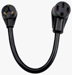
30-to-50 Dogbone Adaptor
At times it becomes necessary to power an RV with a 50 amp service when there is no 50 amp NEMA 1450R receptacle available. Unlike the 30 amp NEMA TT-30R, the 50 amp outlet isn’t an RV-only receptacle so it can be found in residential and industrial applications as well and has a 4 prong outlet that has two hot wires – L1 and L2, as well as a neutral and ground wire. Any RV dealer or RV accessory store will offer an adaptor that is commonly referred to as a 30-to-50 dogbone adaptor, which is illustrated above. This adaptor will let you adapt your 50 amp plug to a 30 amp so that you can plug your 50 amp RV into a 30 amp RV receptacle if that’s all that is available. When you do this you’ll be limited to 30 amps of power though. The dogbone adaptor will connect the single 120 volt hot pole to both the L1 and L2 inputs of your RV’s 50 amp breaker panel. When you do this you will have the same phase across L1 and L2 so there will be no 240 volts available. But, seeing as how 99.9% of the RVs made don’t use anything with 240 volts that’s not a problem. In this situation all of the power will be going down the neutral wire. But, you are only sending 30 amps to the panel and your neutral wire is rated to handle 50 amps so you’ll be fine. You will have to be careful to manage your loads when running on 30 amps. If you fire up all of your air conditioners and water heater you are going to trip that 30 amp pedestal breaker real quick so you have to watch what you turn on. You can also add a second adaptor to change the 30 amp down to a 20 amp plug if you have to but then all you’re going to be able to do is keep the batteries charged and maybe run a few lights.
That’s it for this month. Be sure to check out next month’s installment that covers transfer switches, generators, batteries and chargers, and low voltage circuits. We’ll explain how they work and how to test them should something fail.

Mark Quasius is the founder of RVtechMag.com, the past Midwest editor of RV Magazine, writes for numerous RV-related publications and a regular Contributor to FMCA’s Family RVing Magazine. Mark and his wife Leann travel in their 2016 Entegra Cornerstone.